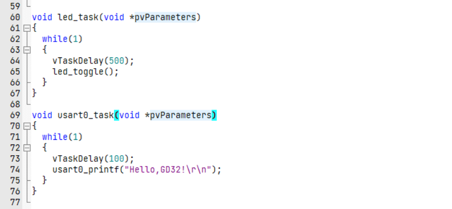
项目地址:
https://github.com/kings669/GD32F310-FreeRTOS
项目说明
本次项目依靠环境为FreeRTOS,如需移植可移步文章:【GD32F310开发板试用】GD32F310移植FreeRTOS在Github中,有本项目的所有源码及资料。
完成情况:
- 完成对Usart的初始化
- 完成Printf的映射
代码
代码部分的风格按照原来在STM32上的写法。
usart.c
#include "usart.h"
#include "gpio.h"

UART_HandleTypeDef usart0;

void My_Usart_Init(void)
{
    /* USART configure */
    usart0.usart_periph = USART0;
    usart0.Init.BaudRate = 115200U;
    usart0.Init.WordLength = USART_WL_8BIT;
    usart0.Init.StopBits = USART_STB_1BIT;
    usart0.Init.Parity = USART_PM_NONE;

    usart_deinit(usart0.usart_periph);
    usart_baudrate_set(usart0.usart_periph,usart0.Init.BaudRate);
    usart_word_length_set(usart0.usart_periph,usart0.Init.WordLength);
    usart_stop_bit_set(usart0.usart_periph,usart0.Init.StopBits);
    usart_parity_config(usart0.usart_periph,usart0.Init.Parity);
    usart_receive_config(usart0.usart_periph,USART_RECEIVE_ENABLE);
    usart_transmit_config(usart0.usart_periph,USART_TRANSMIT_ENABLE);
    usart_enable(usart0.usart_periph);
    usart_interrupt_enable(usart0.usart_periph, USART_INT_RBNE);
    usart_interrupt_enable(usart0.usart_periph, USART_INT_ERR);
    nvic_irq_enable(USART0_IRQn,0,0);
}

void My_Usart_MspInit(void)
{
    GPIO_InitTypeDef GPIO_InitStruct = {0};

    /*GPIO Port Clock Enable */
    rcu_periph_clock_enable(RCU_GPIOA);
    /*Usart0 Clock Enable */
    rcu_periph_clock_enable(RCU_USART0);

    /**USART0 GPIO Configuration
   PA10    ------> USART0_RX
   PA9     ------> USART0_TX
   */
    /*Configure GPIO pin : PtPin  PA9*/
    GPIO_InitStruct.gpio_periph = GPIOA;
    GPIO_InitStruct.mode = GPIO_MODE_AF;
    GPIO_InitStruct.pin = GPIO_PIN_9;
    GPIO_InitStruct.otype = GPIO_OTYPE_PP;
    GPIO_InitStruct.speed = GPIO_OSPEED_50MHZ;
    GPIO_InitStruct.pull_up_down = GPIO_PUPD_PULLUP;
    GPIO_InitStruct.alt_func_num=GPIO_AF_1;
    gpio_af_set(GPIO_InitStruct.gpio_periph,GPIO_InitStruct.alt_func_num,GPIO_InitStruct.pin);
    gpio_mode_set(GPIO_InitStruct.gpio_periph,GPIO_InitStruct.mode,GPIO_InitStruct.pull_up_down,GPIO_InitStruct.pin);
    gpio_output_options_set(GPIO_InitStruct.gpio_periph,GPIO_InitStruct.otype,GPIO_InitStruct.speed,GPIO_InitStruct.pin);
    /*Configure GPIO pin : PtPin  PA10*/
    GPIO_InitStruct.gpio_periph = GPIOA;
    GPIO_InitStruct.mode = GPIO_MODE_AF;
    GPIO_InitStruct.pin = GPIO_PIN_10;
    GPIO_InitStruct.otype = GPIO_OTYPE_PP;
    GPIO_InitStruct.speed = GPIO_OSPEED_50MHZ;
    GPIO_InitStruct.pull_up_down = GPIO_PUPD_PULLUP;
    GPIO_InitStruct.alt_func_num=GPIO_AF_1;
    gpio_af_set(GPIO_InitStruct.gpio_periph,GPIO_InitStruct.alt_func_num,GPIO_InitStruct.pin);
    gpio_mode_set(GPIO_InitStruct.gpio_periph,GPIO_InitStruct.mode,GPIO_InitStruct.pull_up_down,GPIO_InitStruct.pin);
    gpio_output_options_set(GPIO_InitStruct.gpio_periph,GPIO_InitStruct.otype,GPIO_InitStruct.speed,GPIO_InitStruct.pin);
}
usart.h
#ifndef __USART_H_
#define __USART_H_

#include "main.h"

/**
  * @brief UART Init Structure definition
  */
typedef struct
{
  uint32_t BaudRate;                  /*!< This member configures the UART communication baud rate.
                                           The baud rate is computed using the following formula:
                                           - IntegerDivider = ((PCLKx) / (8 * (OVR8+1) * (huart->Init.BaudRate)))
                                           - FractionalDivider = ((IntegerDivider - ((uint32_t) IntegerDivider)) * 8 * (OVR8+1)) + 0.5
                                           Where OVR8 is the "oversampling by 8 mode" configuration bit in the CR1 register. */

  uint32_t WordLength;                /*!< Specifies the number of data bits transmitted or received in a frame.
                                           This parameter can be a value of @ref UART_Word_Length */

  uint32_t StopBits;                  /*!< Specifies the number of stop bits transmitted.
                                           This parameter can be a value of @ref UART_Stop_Bits */

  uint32_t Parity;                    /*!< Specifies the parity mode.
                                           This parameter can be a value of @ref UART_Parity
                                           @note When parity is enabled, the computed parity is inserted
                                                 at the MSB position of the transmitted data (9th bit when
                                                 the word length is set to 9 data bits; 8th bit when the
                                                 word length is set to 8 data bits). */

  uint32_t Mode;                      /*!< Specifies whether the Receive or Transmit mode is enabled or disabled.
                                           This parameter can be a value of @ref UART_Mode */

  uint32_t HwFlowCtl;                 /*!< Specifies whether the hardware flow control mode is enabled or disabled.
                                           This parameter can be a value of @ref UART_Hardware_Flow_Control */

  uint32_t OverSampling;              /*!< Specifies whether the Over sampling 8 is enabled or disabled, to achieve higher speed (up to fPCLK/8).
                                           This parameter can be a value of @ref UART_Over_Sampling */
} UART_InitTypeDef;
/**
  * @brief  UART handle Structure definition
  */
typedef struct __UART_HandleTypeDef
{
  uint32_t usart_periph;        /*!< UART registers base address        */
  UART_InitTypeDef Init;             /*!< UART communication parameters      */
} UART_HandleTypeDef;

extern UART_HandleTypeDef usart0;;

extern void My_Usart_Init(void);
extern void My_Usart_MspInit(void);

#endif
bsp_usart.c
#include "bsp_usart.h"
#include "usart.h"
#include <stdio.h>
#include <stdarg.h>
#include "string.h"
uint8_t usart0_buf[128];
uint16_t len = 0,i;
//printf redefine
void usart0_printf(const char *fmt,...)
{
static va_list ap;
va_start(ap, fmt);
vsprintf((char *)usart0_buf, fmt, ap);
va_end(ap);
len = strlen((const char *)usart0_buf);
for(i=0;i<len;i++)
{
while (RESET == usart_flag_get(usart0.usart_periph,USART_FLAG_TC));//Ñ»··¢ËÍ,Ö±µ½·¢ËÍÍê±Ï
usart_data_transmit(usart0.usart_periph,(uint32_t)usart0_buf[i]);
}
}
uint8_t value;
void USART0_IRQHandler(void)
{
if(RESET != usart_interrupt_flag_get(usart0.usart_periph, USART_INT_FLAG_RBNE))
{
/* receive data */
value = (uint8_t)usart_data_receive(usart0.usart_periph);
usart_interrupt_flag_clear(usart0.usart_periph,USART_INT_FLAG_ERR_FERR);
}
}
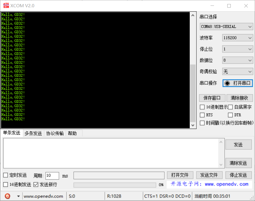
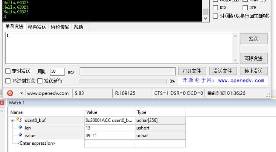
测试部分
其它
在编写过程中,经常报内存的错误。经过编译后,Program Size: Code=14824 RO-data=368 RW-data=160 ZI-data=7856。ROM=14.85KB,RAM=7.83KB,可怜的板子,承受了它不能承受之痛😂


