MM32F5270 是基于安谋科技的 Armv-8 架构的“星辰”STAR-MC1 处理器开发的 32 位微控制器产品.本篇文章通过调用MindSDK例程查看内部集成电路接口IIC。
1、环境配置
原本我的keil版本不能兼容MM32F5277E9P芯片包,拿到开发板当天激动的直接添加,结果就是添加芯片包成功,keil的options->target里面也能识别出MindMotion MM32F5277E9P,但是编译却会报错,经过查阅官方资料以及群友的提醒,将keil升级到5.37(必须为5.37及以上,将编译器换成version6)。 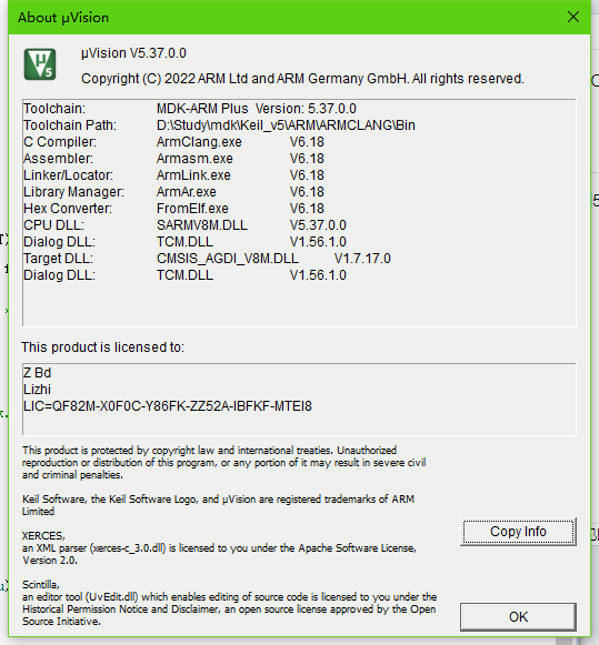
之后再添加芯片包,编译hello world demo 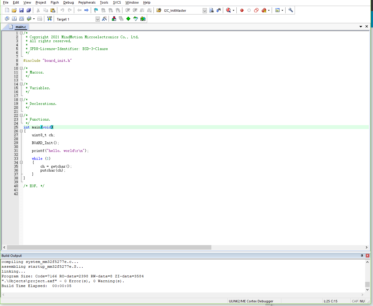
可以看到 0错误 0警告
将套件中附赠的PWLINK2的烧录器与开发板接上,keil options debug中按如下配置 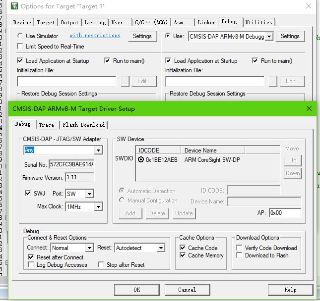
引脚口在带灵动微MM32F5的Plus-F5270开发板怎么玩已有说明,接上即可。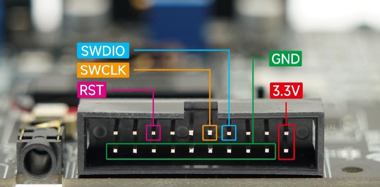
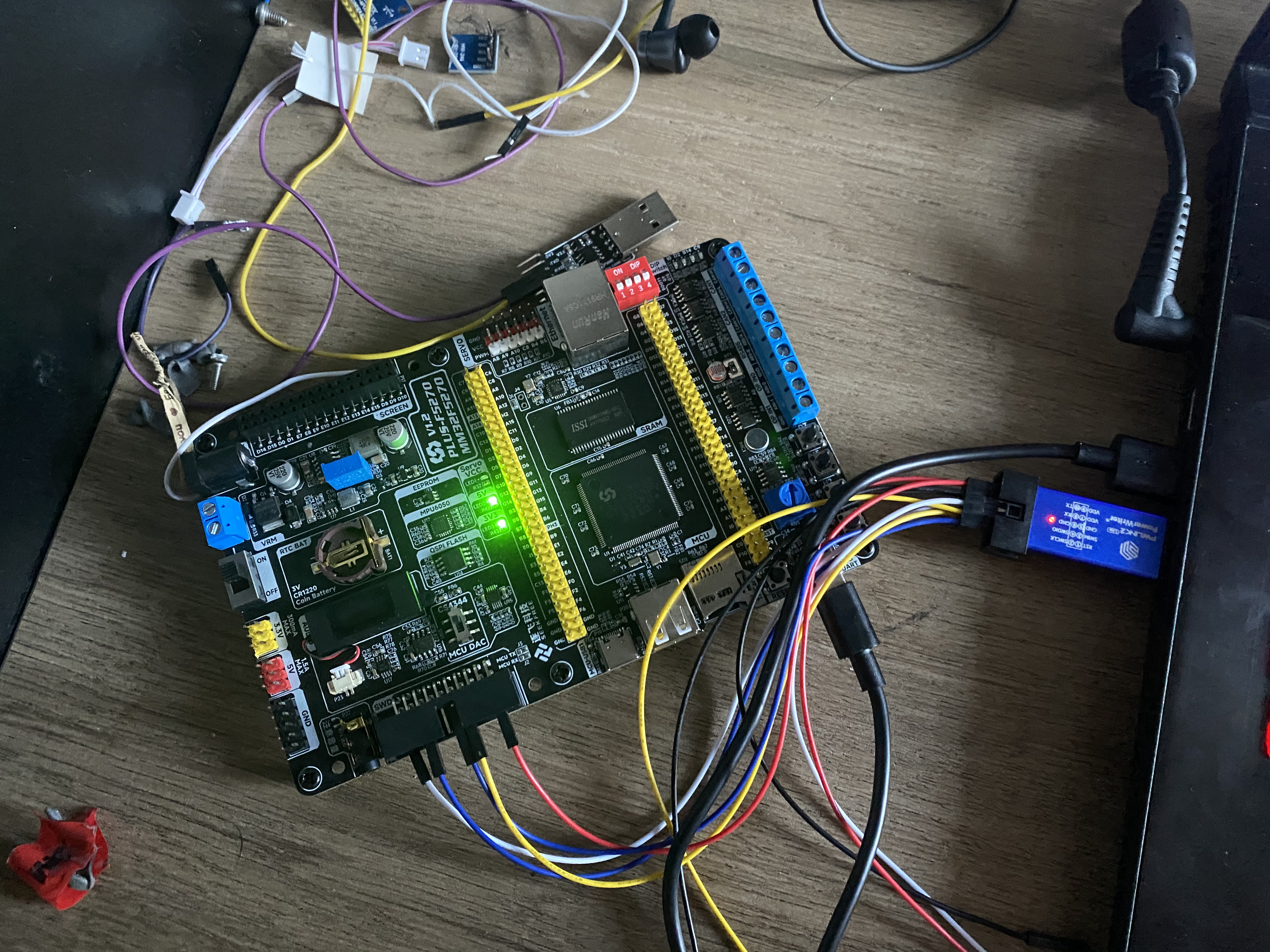
烧录程序

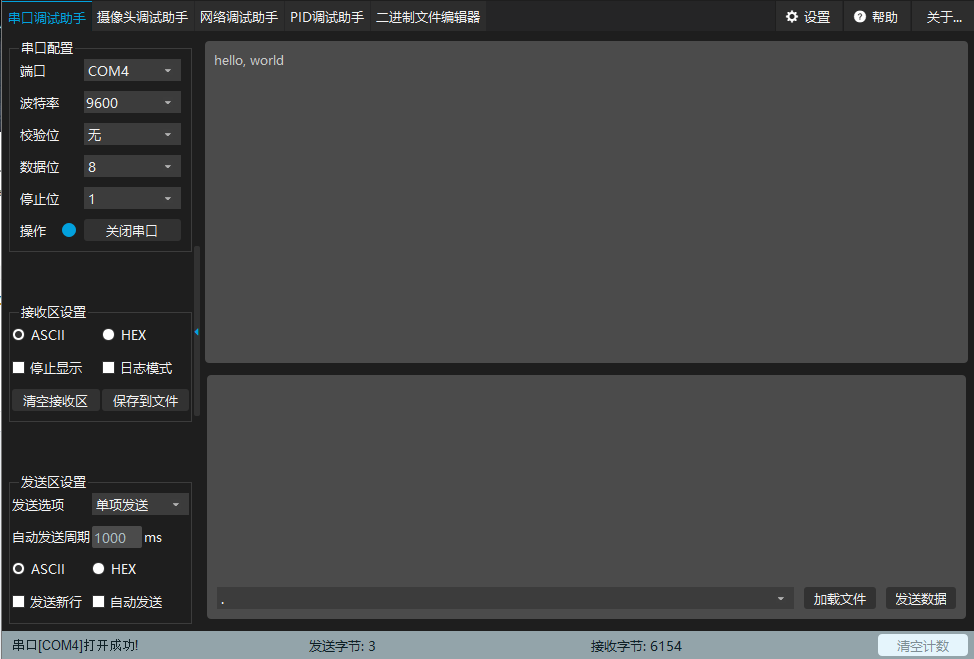
打开串口程序,配置波特率为9600,8位数据位,1位停止位,无校验位,可以看到成功打印hello,world
2、测试硬件IIC
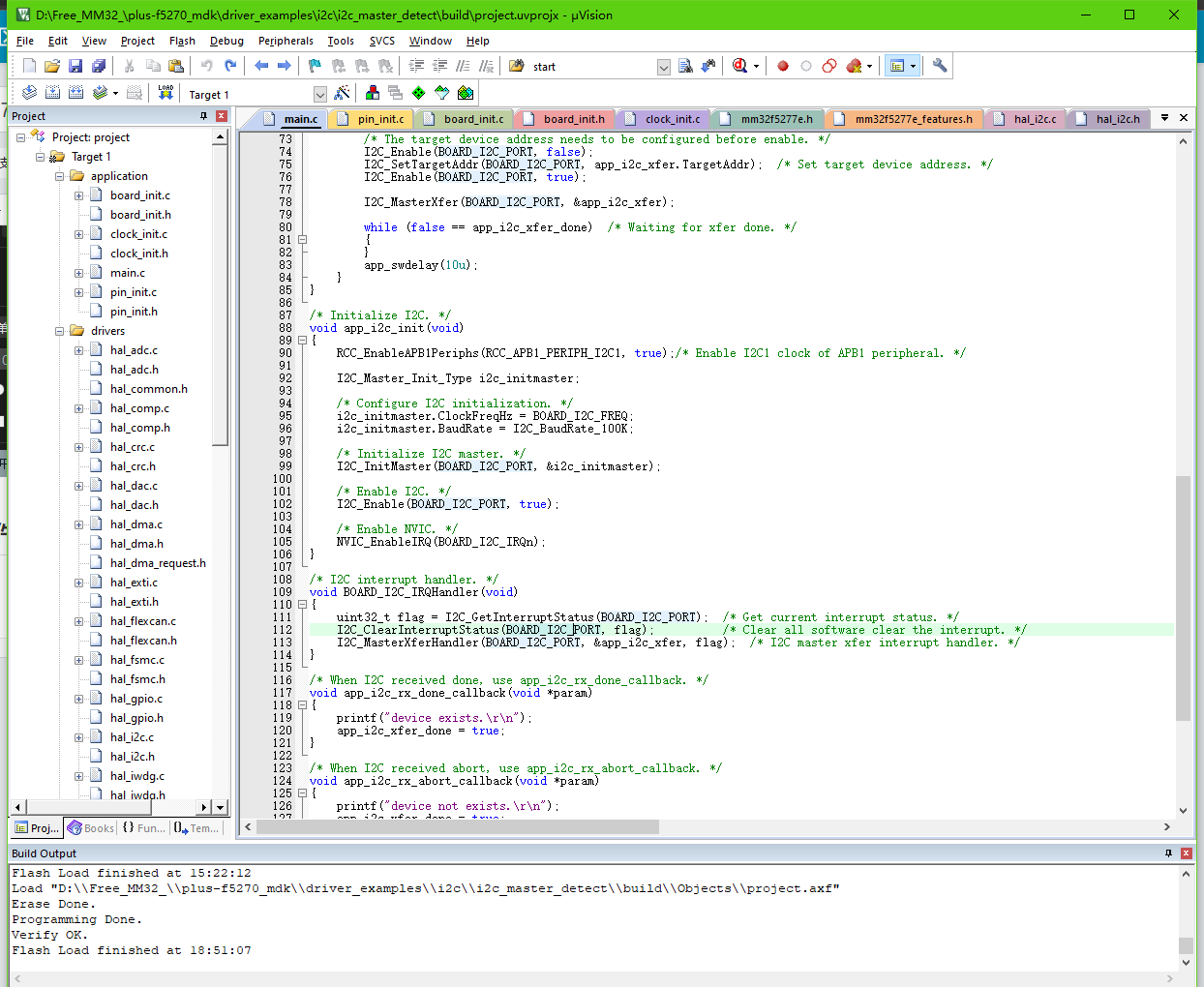
环境配置完成,接下来烧写MindSDK自带的IIC例程
static I2C_MasterXfer_Type app_i2c_xfer;
volatile static bool app_i2c_xfer_done;  /* Xfer done flag. */
static uint8_t app_i2c_rx_buf[APP_I2C_BUF_LEN];  /* I2C rx buffer. */
static uint8_t app_i2c_tx_buf[APP_I2C_BUF_LEN];  /* I2C tx buffer. */

/*
* Declerations.
*/
void app_i2c_init(void);
void app_i2c_detect(void);
void app_i2c_rx_abort_callback(void *param);
void app_i2c_rx_done_callback(void *param);
void app_swdelay(uint32_t ms);

/*
* Functions.
*/
int main(void)
{
 BOARD_Init();
 printf("i2c_master_detect example.\r\n");

 /* Initialize I2C. */
 app_i2c_init();

 while (1)
 {
 printf("press any key to detect I2C.\r\n");
 getchar();
 app_i2c_detect();  /* Detect operation. */
 }
}

/* Detect the operation of write and read. */
void app_i2c_detect()
{
 for (uint16_t i = 0x00u; i <= 0xFEu; i += 2u)  /* 7bit address is (device address >> 1) ,so judge next address need add 2 in address now. */
 {
 printf("target: 0x%02X, ", i);

 app_i2c_xfer.TargetAddr = i >> 1u;          /* Setup target deveice address. */
 app_i2c_xfer.Direction = I2C_Direction_Rx;  /* Setup the xfer direction. */
 app_i2c_xfer.TxBuf = app_i2c_tx_buf;        /* Setup xfer buffer. */
 app_i2c_xfer.RxBuf = app_i2c_rx_buf;        /* Setup rx buffer. */
 app_i2c_xfer.TxLen = APP_I2C_TX_LEN;      /* Setup xfer buffer data length. */
 app_i2c_xfer.RxLen = APP_I2C_RX_LEN;      /* Setup xfer buffer data length. */
 app_i2c_xfer.AbortCallback = app_i2c_rx_abort_callback;  /* Receive abort callback. */
 app_i2c_xfer.DoneCallback = app_i2c_rx_done_callback;    /* Receive done callback. */
 app_i2c_xfer_done = false;                  /* Setup xfer done flag to xfer not done. */

 /* The target device address needs to be configured before enable. */
 I2C_Enable(BOARD_I2C_PORT, false);
 I2C_SetTargetAddr(BOARD_I2C_PORT, app_i2c_xfer.TargetAddr);  /* Set target device address. */
 I2C_Enable(BOARD_I2C_PORT, true);

 I2C_MasterXfer(BOARD_I2C_PORT, &app_i2c_xfer);

 while (false == app_i2c_xfer_done)  /* Waiting for xfer done. */
 {
 }
 app_swdelay(10u);
 }
}

/* Initialize I2C. */
void app_i2c_init(void)
{
 RCC_EnableAPB1Periphs(RCC_APB1_PERIPH_I2C1, true);/* Enable I2C1 clock of APB1 peripheral. */

 I2C_Master_Init_Type i2c_initmaster;

 /* Configure I2C initialization. */
 i2c_initmaster.ClockFreqHz = BOARD_I2C_FREQ;
 i2c_initmaster.BaudRate = I2C_BaudRate_100K;

 /* Initialize I2C master. */
 I2C_InitMaster(BOARD_I2C_PORT, &i2c_initmaster);

 /* Enable I2C. */
 I2C_Enable(BOARD_I2C_PORT, true);

 /* Enable NVIC. */
 NVIC_EnableIRQ(BOARD_I2C_IRQn);
}

/* I2C interrupt handler. */
void BOARD_I2C_IRQHandler(void)
{
 uint32_t flag = I2C_GetInterruptStatus(BOARD_I2C_PORT);  /* Get current interrupt status. */
 I2C_ClearInterruptStatus(BOARD_I2C_PORT, flag);          /* Clear all software clear the interrupt. */
 I2C_MasterXferHandler(BOARD_I2C_PORT, &app_i2c_xfer, flag);  /* I2C master xfer interrupt handler. */
}

/* When I2C received done, use app_i2c_rx_done_callback. */
void app_i2c_rx_done_callback(void *param)
{
 printf("device exists.\r\n");
 app_i2c_xfer_done = true;
}

/* When I2C received abort, use app_i2c_rx_abort_callback. */
void app_i2c_rx_abort_callback(void *param)
{
 printf("device not exists.\r\n");
 app_i2c_xfer_done = true;
}

/* Software delay millisecond. */
void app_swdelay(uint32_t ms)
{
 for (uint32_t i = 0u; i < ms; i++)
 {
 for (uint32_t j = 0u; j < (CLOCK_SYS_FREQ / 1000u); j++)
 {
 __NOP();
}
 }
}
烧写成功,打开串口 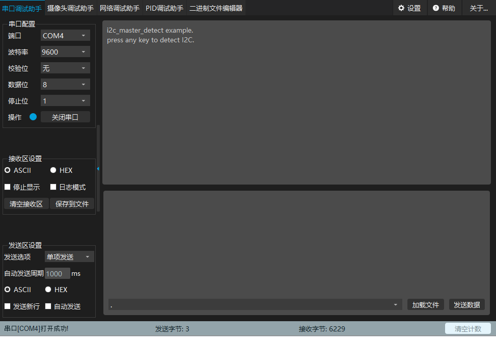
按照源码的逻辑,输入任意值即可检测,这里我输入1 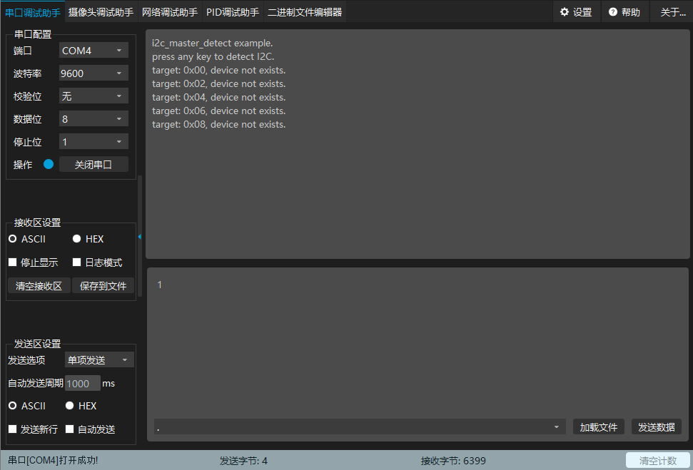
可以看到检测到0xA0设备地址了
总结
MindSDK集成了大部分外设库文件,快速上手开发神器,最近时间过于仓促,拿到手后爱不释手(可怜学生党),也没有空余的时间去体验开发板的其他功能,好在有强大的MindSDK的强大助力,等这段时间实习的事情忙完后,再来把MM32F5270系统开发一遍。

