前言
首先很高兴能够入选兆易创新GD32F427V的开发板试用名单,该系列采用ARM Cortex-M4内核,主频高达240MHz,带浮点协处理器,支持复杂运算的嵌入式应用,并具备更实时的处理能力。GD32F4新产品配备了512KB到3072KB片上Flash,和大容量片上SRAM,更好的支持了多种应用场景。 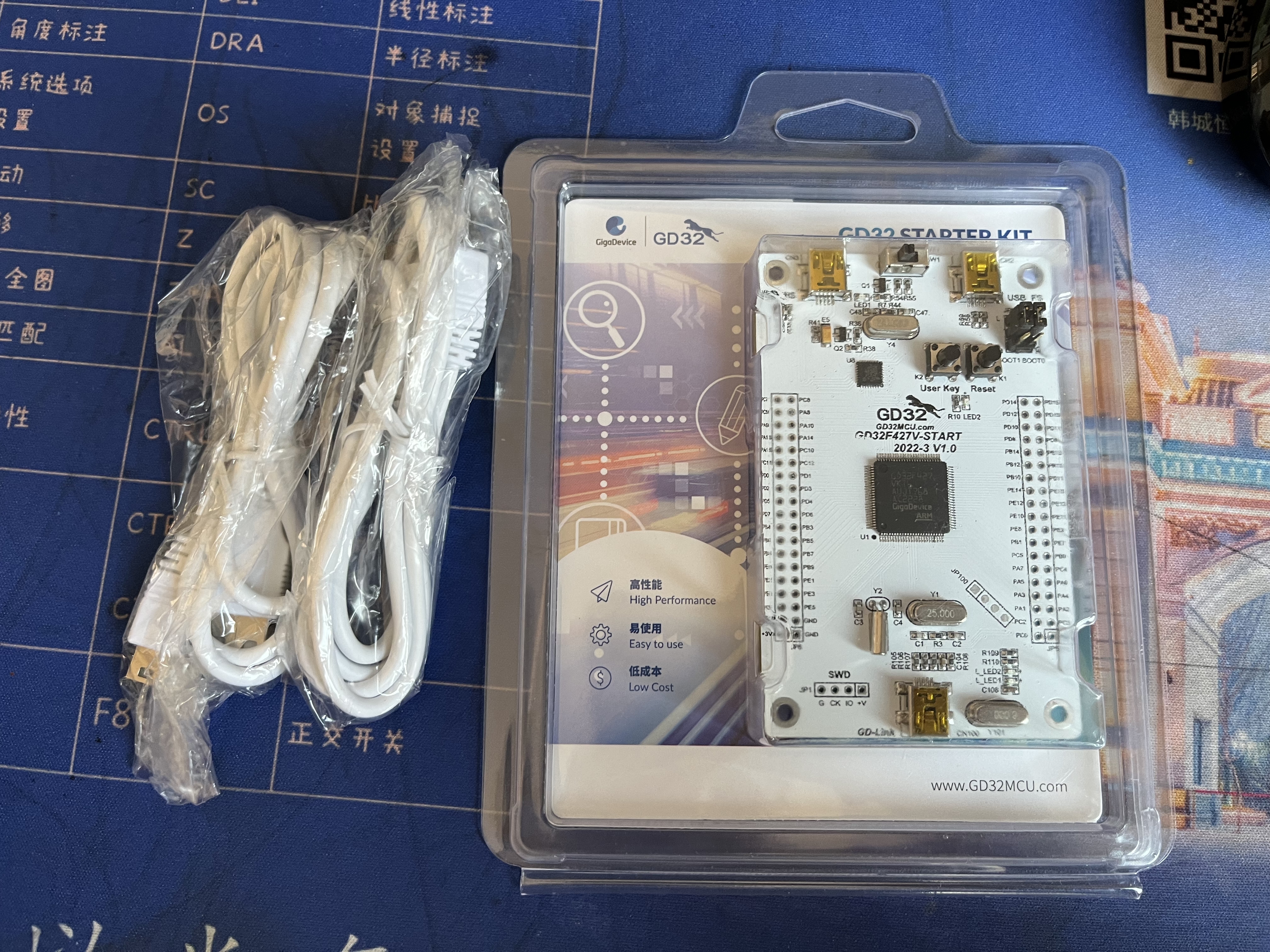
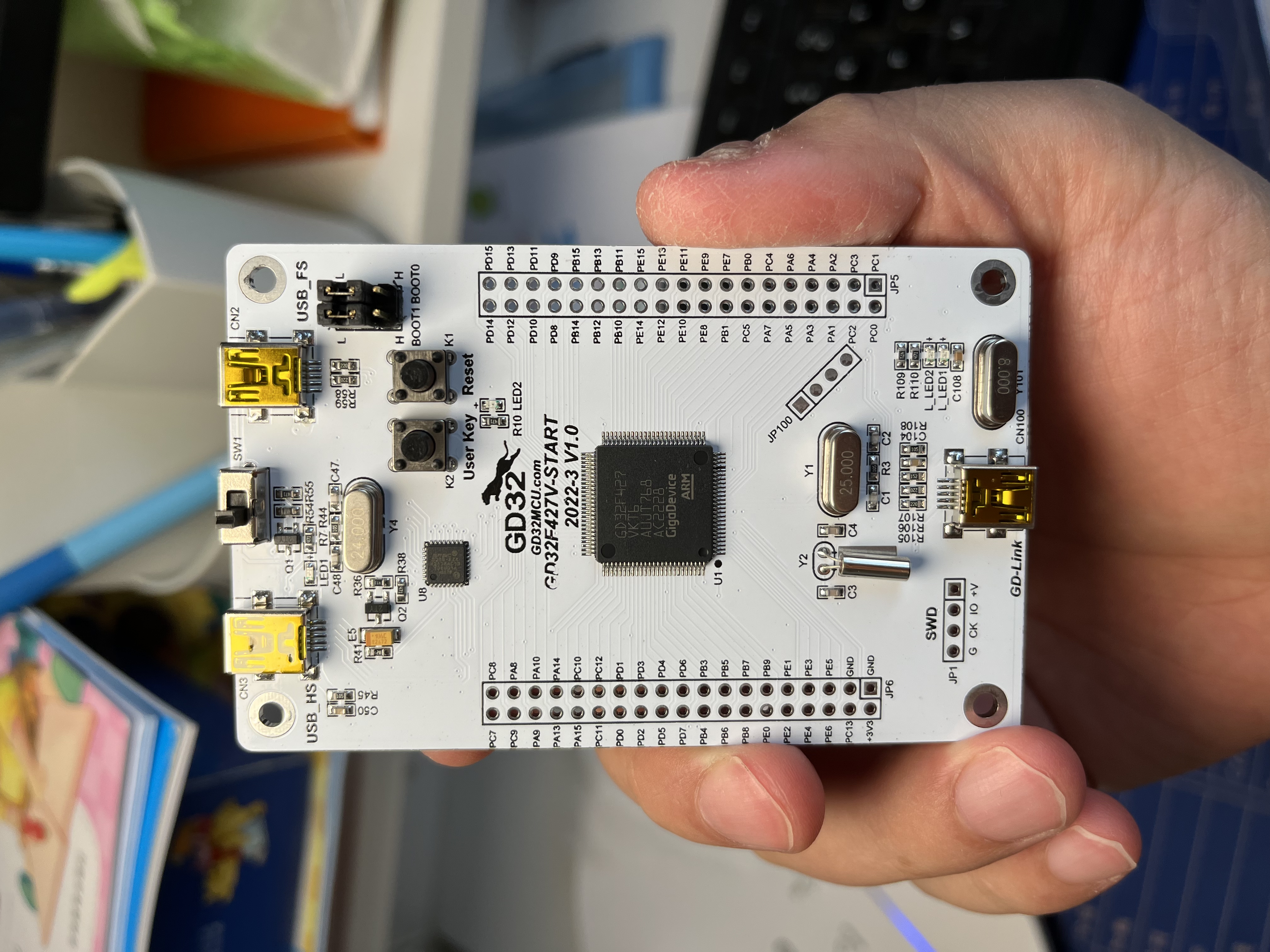
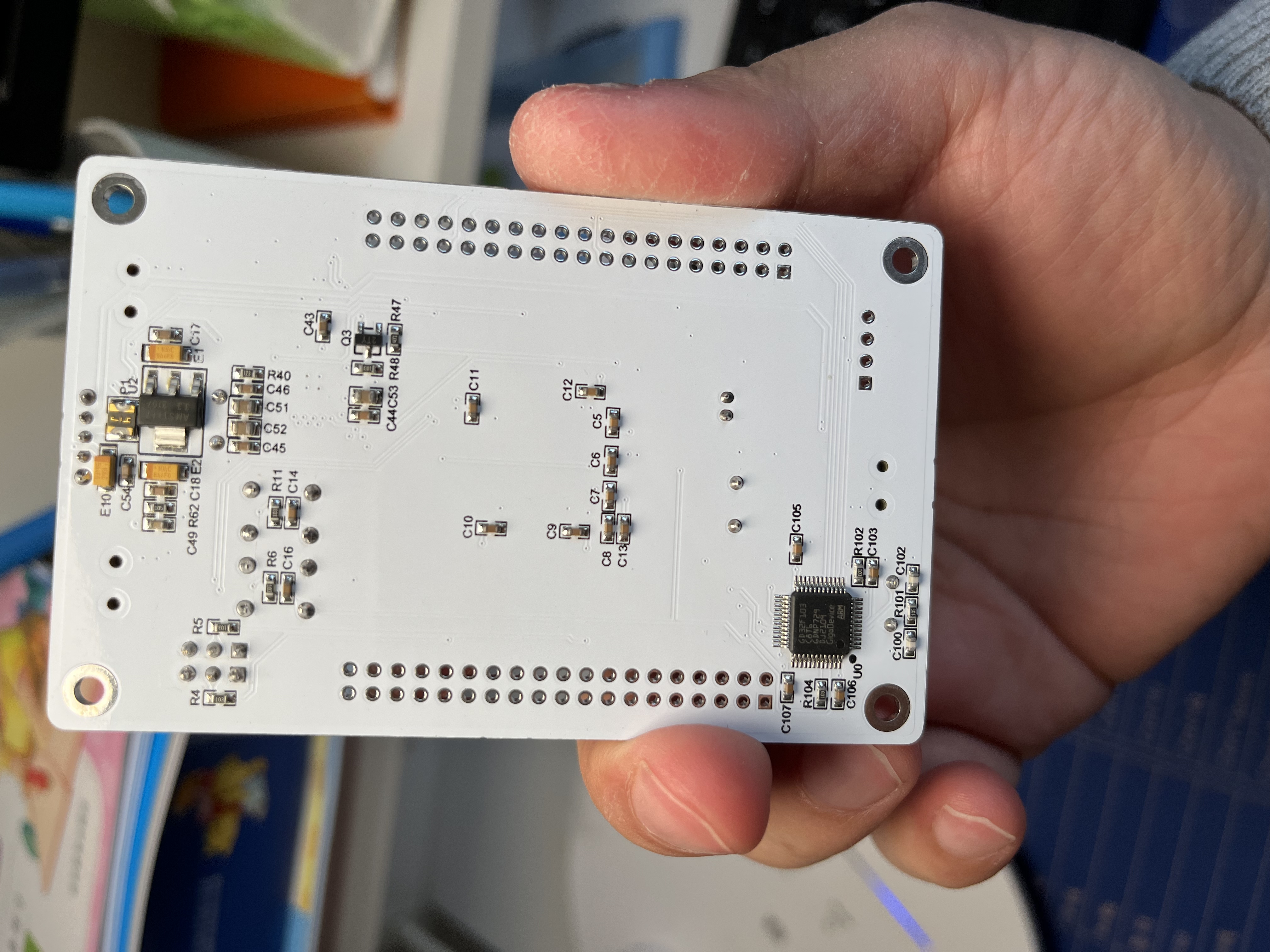
开发板很漂亮,纯白做工很细腻,开发板是一块核心板,板载了gdlink,免去了寻找调试器的烦恼,同时板载了晶振,使得程序运行更加精准。板载了USB FS和HS,并且HS带phy使得更加易用。开发板目前已经较为完美,但在试用过程中,还有少量的不足:开发板没有焊接排针并且没有提供排针,其次IO输出的电源引脚只有一个有点少。
试用
拿到开发板开发板以后在跑了一下简单的程序(点灯),熟悉开发环境和下载流程之后,开始了本次系统的开发。本次的例子基于SSD1289主控320x240 的LCD显示屏。对LCD显示屏进行初始化、填充、画点、画线、显示字符、显示汉字和图片。图片是通过上位机将BMP图片转换成二进制bin文件,然后通过串口传输到GD32F427,然后MCU将传输内容写入LCD并显示。开发调用了少量厂家提供固件库,主要以自定义的寄存器访问为主。
本系统应用的MCU管脚有:PA1,2,4,6,7;(注意:GPIOA部分的管脚用于SWD调试,如果不小心修改了输出或者AF会导致调试出现RDDI-Error。这时不要慌,找一个正常的程序(可以用例子),按住复位键,在松开复位键后瞬间下载程序即可恢复。@v@) PB 6,7; PC 6; PE15~0;
    // USART0_TX: PB6
    // USART0_RX: PB7
    // LED:       PC6
    // REST:      PA7,   Reset
    // RS:        PA6,   Data/CMD switch // 0: Register Index; 1: Register Data
    // WR:        PA4,   Write Data     // rising edge active
    // RD:        PA2,   Read Data     // low active
    // CS:        PA1,   Chip Select    // low active
    // GPIOE15~0:  PE15~0, Data Bus
时钟配置采用了板上25MHz晶振时钟,MCU工作在240MHz,APB1工作在120MHz,APB2工作在60MHz。
串口配置如下:rs232,8位,无校验,波特率:921600bps,配置代码如下:
 typedef struct {
        IO STAT0;         // 0x00, Status Register 0
                          // [31:30]:
                          //     [9]: CTSF, rc_w0
                          //     [8]: LBDF, rc_w0
                          //     [7]: TBE, r
                          //     [6]: TC, rc_w0
                          //     [5]: RBNE, rc_w0
                          //     [4]: IDELF, r
                          //     [3]: ORERR, r
                          //     [2]: NERR, r
                          //     [1]: FERR, r
                          //     [0]: PERR, r
        IO DATA;          // 0x04, Data Register
                          //   [8:0]: DATA, rw
        IO BAUD;          // 0x08, BAUD Register
                          //  [15:4]: INTDIV[11:0]
                          //   [3:0]: FRADIV[3:0]
        IO CTL0;          // 0x0C, Control Register 0
                          //    [15]: OVSMOD, Over Sample mode 0: 16 sample; 1: 8 sample
                          //    [13]: UEN, USART Enable. 1: enable
                          //    [12]: WL, Word Length: 0: 8 bit; 1: 9bit
                          //    [11]: WM, wakeup mode: 0: idle line; 1: address match
                          //    [10]: PCEN, Parity ctrl enable: 0: Disable parity; 1: Enable parity
                          //     [9]: PM, Parity mode: 0: Even; 1: odd
                          //     [8]: PERRIE, parity Error Int enable: 0: disable; 1: enable
                          //     [7]: TBEIE, Transfer Buffer Empty Int enable
                          //     [6]: TCIE, Transfter complete Int enable
                          //     [5]: RBNEIE, Read buffer not empty int enable
                          //     [4]: IDELIE, Idle line detect int enable
                          //     [3]: TEN, Transmit Enable
                          //     [2]: REN, Receive Enable
                          //     [1]: RWU, Receive Wakeup from silence, 0: Normal; 1: Silence
                          //     [0]: SBKCMD, Send break Frame: 0: no break frame; 1: Send Break Frame
        IO CTL1;          // 0x10, Control Register 1
                          //    [14]: LMEN, Lin mode: 0: disable
                          // [13:12]: STB, Stop len, 00: 1 stop; 01: 0.5 stop; 10: 2 stop; 11: 1.5 stop
                          //    [11]: CKEN, CK PIN Enable, 0: Disable
                          //    [10]: CPL, Clock pole 0: CK Keep low; 1: CK keep high
                          //     [9]: CPH, Clock Phase, 0: sample first data at first edge. 1: second edge
                          //     [8]: CLEN, CK signal length: 0: 8bit frame have 7 ck pulse, 9 bit frame have 8 ck pulse
                          //                                  1: 8bit frame have 8 ck pulse, 9 bit frame have 9 ck pulse
                          //     [6]: LBDIE, LIN break signal detect int enable;
                          //     [5]: LBLEN, LIN break frame len: 0: 10bit; 1: 11 bit
                          //   [3:0]: ADDR[3:0], USART addresss, WM =1use;
        IO CTL2;          // 0x14, Control Register 2
                          //    [11]: OSB, 1 data bit sample once
                          //    [10]: CTSIE, CTS Interrupt Enable
                          //     [9]: CTSEN, CTS Enable
                          //     [8]: RTSEN, RTS Enable
                          //     [7]: DENT, DMA Transmit Enable
                          //     [6]: DENR, DMA Receive Enable
                          //     [5]: SCEN, Smart Card Enable
                          //     [4]: NKEN, Smart Card Nack enable
                          //     [3]: HDEN, half duplex mode
                          //     [2]: IRLP, IrDA low power mode: 0: Normal mode; 1: Low-power mode
                          //     [1]: IREN, IrDA Enable
                          //     [0]: ERRIE, Error Interrupt enable
        IO GP;            // 0x18, Protect Time and Prescale Register
                          //  [15:8]: GUART[7:0], Smart Card mode protect time
                          //   [7:0]: PSC[7:0], IrDA mode, divide freq parameter
         O Reserved0[25]; // 0x1C~0x7C, Reserved
        IO CTL3;          // 0x80, Control Register 3
                          //    [11]: MSBF, MSB First
                          //    [10]: DINV, Data bit inverse
                          //     [9]: TINV, TX Pin level invese
                          //     [8]: RINV, RX Pin Level inv
                          //     [5]: EBIE, End block Flag interrupt enable
                          //     [4]: RTIE, Receive out of time Int enable
                          //   [3:1]: SCRTNUM, Smart card auto retry number
                          //     [0]: RTEN, Receiver run out of time
        IO RT;            // 0x84, Receive out of time Reigster
                          // [31:24]: BL, Block length
                          //  [23:0]: RT, Receive out of time threshold
        IO STAT1;         // 0x88, Status Register 1
                          //    [16]: BSY, Busy status
                          //    [12]: EBF, End of Block flag
                          //    [11]: RTF, Receive Out of time Flag
         O Reserved1[21]; // 0x8C~0xDC, Reserved
        IO CHC;           // 0xC0, Compact control
                          //     [8]: EPERR, Parity Error ealy detect flag
                          //     [2]: BCM, Break frame compact mode
                          //     [1]: PCM, parity Compact mode
                          //     [0]: HCM, Hardware flow control Compact mode
    } USART_TYPEDEF;

          串口的初始化如下:

    // USARTDIV = 120000000 / 8 / 921600 = 16.276041666
    //    INTDIV = 16 = 0x10
    //    FRADIV = 0.276041666 * 8 = 2.2 = 0x2

    #define USARTDIV_8X_120MHz_921600 0x102


    void UART_INIT(USART_TYPEDEF *uart){
        uint16_t tmp;
        // UEN
        uart->CTL0 |= (0x1 << 13);
        // Sample mode: 8 sample: 0x1 << 15
        // Data len: WL : 8 bit(last bit use for parity) 0x0 <<  12
        // no parity: PCEN: 0x0 << 10
      //            PM:   0x0 << 9
      tmp = (0x1 << 15); //| (0x0 <<12) | (0x0 <<10);
      uart->CTL0 |= tmp;
      // STB: 1 stop 0x0 << 12
      // USARTDIV = 120000000 / 8 / 115200 = 130.2083333
      //    INTDIV = 130 = 0x82
      //    FRADIV = 0.2083 * 8 = 1.6 = 0x2
      // USARTDIV = 120000000 / 16 / 115200 = 65.10416666
      //    INTDIV = 65 = 0x41
      //    FRADIV = 0.104166 * 16 = 1.67 = 0x2
      // USART_BAUD = 0x822
        uart->BAUD = USARTDIV_8X_120MHz_921600;
        // Enable Tx en and Rx EN
        uart->CTL0 |= (0x1 <<2) | (0x1<<3);

    }
    void UART_putc(USART_TYPEDEF *uart, uint8_t ch){
        while(!(uart->STAT0 & USART_STAT0_TBE)) ; //Transmit data register not empty
        uart->DATA = ch;
    }
    uint8_t UART_getc(USART_TYPEDEF *uart){
        while(!(uart->STAT0 & USART_STAT0_RBNE)) ;// Receive data register is not empty
        return (uint8_t)uart->DATA;
    }
LCD部分:
#define LCD_DataPort GPIOE->ODR
    #define LCD_READ_DataPort GPIOE->IDR

    void SET_LCD_REST(void) {
        GPIOA->BSRR = (0x1 << 7);
    }

    void CLR_LCD_REST(void) {
        GPIOA->BRR = (0x1 << 7);
    }

    void SET_LCD_RS(void) {
        GPIOA->BSRR = (0x1 << 6);
    }

    void CLR_LCD_RS(void) {
        GPIOA->BRR = (0x1 << 6);
    }

    void SET_LCD_WR(void) {
        GPIOA->BSRR = (0x1 << 4);
    }

    void CLR_LCD_WR(void) {
        GPIOA->BRR = (0x1 << 4);
    }

    void SET_LCD_RD(void) {
        GPIOA->BSRR = (0x1 << 2);
    }

    void CLR_LCD_RD(void) {
        GPIOA->BRR = (0x1 << 2);
    }

    void SET_LCD_CS(void) {
        GPIOA->BSRR = (0x1 << 1);
    }

    void CLR_LCD_CS(void) {
        GPIOA->BRR = (0x1 << 1);
    }

    void CHANGE_DATA_READ(void){
        GPIOE->MODER = 0x0;
    }


    void CHANGE_DATA_WRITE(void){
        GPIOE->MODER = 0x55555555;
    }

    static __inline void LCD_WRITE_BUS_W16(uint16_t data)
    {
        CLR_LCD_CS();
        LCD_DataPort = data;
        CLR_LCD_WR();
        SET_LCD_WR();
        SET_LCD_CS();
    }

    void LCD_WRITE_DATA(uint16_t data)
    {
        SET_LCD_RS();
        LCD_WRITE_BUS_W16(data);
    }

    void LCD_WRITE_REG(uint16_t REG)
    {
        CLR_LCD_RS();
        LCD_WRITE_BUS_W16(REG);
    }

    void LCD_WRITE_REG_DATA(uint16_t REG, uint16_t data)
    {
        LCD_WRITE_REG(REG);
        LCD_WRITE_DATA(data);
    }

    uint16_t LCD_READ_BUS_W16(void)
    {
        uint16_t tmp_data;
        CHANGE_DATA_READ();
        CLR_LCD_RD();
        CLR_LCD_CS();
        tmp_data = (uint16_t)LCD_READ_DataPort;
        SET_LCD_CS();
        CHANGE_DATA_WRITE();
        return tmp_data;
    }

    uint16_t LCD_READ_DEVICE_CODE (void)
    {
        uint16_t ret_val;
        CLR_LCD_RS();
        ret_val = LCD_READ_BUS_W16();
        return ret_val;
    }


    uint16_t LCD_READ_DATA(void)
    {
        SET_LCD_RS();
        return LCD_READ_BUS_W16();
    }

    uint16_t LCD_READ_REG_DATA(uint16_t REG)
    {
        uint16_t ret_value;
        LCD_WRITE_REG(REG);
        ret_value=LCD_READ_DATA();
        return ret_value;
    }


    void LCD_Init(void)
    {
        SET_LCD_CS();
        SET_LCD_RS();
        SET_LCD_RD();
        SET_LCD_WR();
        CLR_LCD_REST();
        Delay_ms(20);
        SET_LCD_REST();
        Delay_ms(20);
        // 1. open Oscillator

        LCD_WRITE_REG_DATA(0x0000,0x0001);    Delay_ms(1);  //open Oscillator
        // 2. power supply setting
        LCD_WRITE_REG_DATA(0x0003,0xA8A4);    Delay_ms(1);  //0xA8A4
        LCD_WRITE_REG_DATA(0x000C,0x0000);    Delay_ms(1);
        LCD_WRITE_REG_DATA(0x000D,0x080C);    Delay_ms(1);
        LCD_WRITE_REG_DATA(0x000E,0x2B00);    Delay_ms(1);
        LCD_WRITE_REG_DATA(0x001E,0x00B7);    Delay_ms(1);
    //        LCD_WRITE_REG_DATA(0x001E,0x00B0);    Delay_ms(1);
        LCD_WRITE_REG_DATA(0x0001,0x2B3F);    Delay_ms(1);   //320*240  0x6B3F 29EF 2B3F 7A3F
        LCD_WRITE_REG_DATA(0x0002,0x0600);    Delay_ms(1);
        LCD_WRITE_REG_DATA(0x0010,0x0000);    Delay_ms(1);
        LCD_WRITE_REG_DATA(0x0011,0x6070);    Delay_ms(1);   //0x4030  // define data structure 16bit color
        LCD_WRITE_REG_DATA(0x0005,0x0000);    Delay_ms(1);
        LCD_WRITE_REG_DATA(0x0006,0x0000);    Delay_ms(1);
        LCD_WRITE_REG_DATA(0x0016,0xEF1C);    Delay_ms(1);
        LCD_WRITE_REG_DATA(0x0017,0x0003);    Delay_ms(1);
        //LCD_WRITE_REG_DATA(0x0007,0x0233);    Delay_ms(1);
        LCD_WRITE_REG_DATA(0x0007, 0x033);    Delay_ms(1);
        LCD_WRITE_REG_DATA(0x000B,0x0000);    Delay_ms(1);
    //    LCD_WRITE_REG_DATA(0x000B,0x5308);    Delay_ms(1);
        LCD_WRITE_REG_DATA(0x000F,0x0000);    Delay_ms(1);        //scan address start
        LCD_WRITE_REG_DATA(0x0041,0x0000);    Delay_ms(1);
        LCD_WRITE_REG_DATA(0x0042,0x0000);    Delay_ms(1);
        LCD_WRITE_REG_DATA(0x0048,0x0000);    Delay_ms(1);
        LCD_WRITE_REG_DATA(0x0049,0x013F);    Delay_ms(1);
        LCD_WRITE_REG_DATA(0x004A,0x0000);    Delay_ms(1);
        LCD_WRITE_REG_DATA(0x004B,0x0000);    Delay_ms(1);
        LCD_WRITE_REG_DATA(0x0044,0xEF00);    Delay_ms(1);
        LCD_WRITE_REG_DATA(0x0045,0x0000);    Delay_ms(1);
        LCD_WRITE_REG_DATA(0x0046,0x013F);    Delay_ms(1);
        LCD_WRITE_REG_DATA(0x0030,0x0707);    Delay_ms(1);
        LCD_WRITE_REG_DATA(0x0031,0x0204);    Delay_ms(1);
        LCD_WRITE_REG_DATA(0x0032,0x0204);    Delay_ms(1);
        LCD_WRITE_REG_DATA(0x0033,0x0502);    Delay_ms(1);
        LCD_WRITE_REG_DATA(0x0034,0x0507);    Delay_ms(1);
        LCD_WRITE_REG_DATA(0x0035,0x0204);    Delay_ms(1);
        LCD_WRITE_REG_DATA(0x0036,0x0204);    Delay_ms(1);
        LCD_WRITE_REG_DATA(0x0037,0x0502);    Delay_ms(1);
        LCD_WRITE_REG_DATA(0x003A,0x0302);    Delay_ms(1);
        LCD_WRITE_REG_DATA(0x003B,0x0302);    Delay_ms(1);
        LCD_WRITE_REG_DATA(0x0023,0x0000);    Delay_ms(1);
        LCD_WRITE_REG_DATA(0x0024,0x0000);    Delay_ms(1);
        LCD_WRITE_REG_DATA(0x0025,0x8000);    Delay_ms(1);
        LCD_WRITE_REG_DATA(0x004f,0x0000);    Delay_ms(1);        //GDDRAM Y address
        LCD_WRITE_REG_DATA(0x004e,0x0000);    Delay_ms(1);        //GDDRAM X address
        LCD_WRITE_REG(0x0022);
    }

    void LCD_Clear(uint16_t Color)
    {
        uint16_t i,j;
        address_set(0,0,LCD_W-1, LCD_H-1);
        for(i=0;i<LCD_W;i++)
        {
            for(j=0;j<LCD_H;j++)
            {
                LCD_WRITE_DATA(Color);

            }
        }
    }

    // seting LCD display window
    // HSA: Horizontal start address
    // VSA: Vertical start address
    // HEA: Horizontal end address
    // VEA: Vertical end address
    void address_set(uint16_t HSA ,uint16_t VSA, uint16_t HEA, uint16_t VEA)
    {
        LCD_WRITE_REG_DATA(0x0044,(HEA<<8)+HSA);
        LCD_WRITE_REG_DATA(0x0045,VSA);
        LCD_WRITE_REG_DATA(0x0046,VEA);
        LCD_WRITE_REG_DATA(0x004e,HSA);
        LCD_WRITE_REG_DATA(0x004f,VSA);
        LCD_WRITE_REG(0x0022);
    }

    void LCD_Write_Point(uint16_t X, uint16_t Y,uint16_t color)
    {
        LCD_WRITE_REG_DATA(0x004e,X);
        LCD_WRITE_REG_DATA(0x004f,Y);
        LCD_WRITE_REG(0x0022);
        LCD_WRITE_DATA(color);

    }

    uint16_t LCD_Read_Point(uint16_t X, uint16_t Y)
    {
        uint16_t ret_val;
        LCD_WRITE_REG_DATA(0x004e,X);
        LCD_WRITE_REG_DATA(0x004f,Y);
        LCD_WRITE_REG(0x0022);
        ret_val = LCD_READ_DATA();
        ret_val = LCD_READ_DATA(); // GDDRAM data must read twice
        return ret_val;
    }


    // LCD_AREA_FILL: Fill a rectangle area with specified color
    // XSA: X start Point
    // XEA: X End Point
    // YSA:    Y start Point
    // YEA:    Y End Point
    void LCD_AREA_FILL(uint16_t XSA, uint16_t XEA, uint16_t YSA, uint16_t YEA, uint16_t color)
    {
        int i,j;
        address_set(XSA,YSA,XEA,YEA);
        for(i=0;i<= XEA-XSA; i++)
        {
            for(j=0;j<= YEA-YSA; j++)
            {
                LCD_WRITE_DATA(color);
            }
        }
    }

    void LCD_Write_Point_big(uint16_t X, uint16_t Y,uint16_t color)
    {
        LCD_AREA_FILL(X-1,X+1,Y-1,Y+1,color);
    }

    void LCD_DrawLine(uint16_t x1, uint16_t y1, uint16_t x2, uint16_t y2, uint16_t color)
    {
        uint16_t t;
        int xerr=0,yerr=0,delta_x,delta_y,distance;
        int incx,incy,uRow,uCol;

        delta_x=x2-x1; //计算坐标增量
        delta_y=y2-y1;
        uRow=x1;
        uCol=y1;
        if(delta_x>0)incx=1; //设置单步方向
        else if(delta_x==0)incx=0;//垂直线
        else {incx=-1;delta_x=-delta_x;}
        if(delta_y>0)incy=1;
        else if(delta_y==0)incy=0;//水平线
        else{incy=-1;delta_y=-delta_y;}
        if( delta_x>delta_y)distance=delta_x; //选取基本增量坐标轴
        else distance=delta_y;
        for(t=0;t<=distance+1;t++ )//画线输出
        {
            LCD_Write_Point(uRow,uCol,color);//画点
            xerr+=delta_x ;
            yerr+=delta_y ;
            if(xerr>distance)
            {
                xerr-=distance;
                uRow+=incx;
            }
            if(yerr>distance)
            {
                yerr-=distance;
                uCol+=incy;
            }
        }
        Delay_ms(50);
    }

    void LCD_DrawCircle(uint16_t x0, uint16_t y0, uint16_t r,uint16_t color)
    {
        int a, b;
        int di;
        a=0;
        b= r;
        di = 3-(r<<1);
        while(a<=b)
        {
            LCD_Write_Point(x0-b,y0-a,color);//3
            LCD_Write_Point(x0+b,y0-a,color);//0
            LCD_Write_Point(x0-a,y0+b,color);//1
            LCD_Write_Point(x0-b,y0-a,color);//7
            LCD_Write_Point(x0-a,y0-b,color);//2
            LCD_Write_Point(x0+b,y0+a,color);//4
            LCD_Write_Point(x0+a,y0-b,color);//5
            LCD_Write_Point(x0+a,y0+b,color);//6
            LCD_Write_Point(x0-b,y0+a,color);
            a++;
            // use bresenham
            if(di<0) di += 4*a +6;
            else
            {
                di += 10+4*(a-b);
                b --;
            }
            LCD_Write_Point(x0+a,y0+b,color);
        }
    }

    void LCD_DrawRing(uint16_t x0, uint16_t y0, uint16_t r1, uint16_t r2, uint16_t color)
    {
        int i;
        for(i=r1;i<=r2;i++)
        {
            LCD_DrawCircle(x0,y0,i,color);
        }
    }

    void LCD_DrawRectangle(uint16_t x0, uint16_t y0, uint16_t x1, uint16_t y1, uint16_t color)
    {
        LCD_DrawLine(x0,y0,x1,y0,color);
        LCD_DrawLine(x0,y0,x0,y1,color);
        LCD_DrawLine(x0,y1,x1,y1,color);
        LCD_DrawLine(x1,y0,x1,y1,color);
    }


    // Display a character in a defined area
    // num: Character want to display: but " "--->"~"
    // mode: overlay mode(1) or none overlay mode(0)
    void LCD_ShowChar(uint16_t x,uint16_t y,uint8_t num,uint8_t mode,uint16_t color)
    {
        uint8_t temp;
        uint8_t pos,t;
        uint16_t x0=x;
        if(x>LCD_W-16 || y>LCD_H-16)           // area size is not large enough
            return;
        // set window
        num = num - ' ';                       // get offset value from ' ', in ascii

        address_set(x, y, x+8-1, y+16-1);      // set cursor address
        if(!mode) // none overlay mode
        {
            for(pos=0; pos<16; pos++)
            {
                temp=asc2_1608[(uint16_t)num*16+pos];         // call 16x8 font
                for(t=0;t<8;t++)
                {
    //                if(temp&0x01)
    //                    POINT_COLOR=colortemp;
    //                else
    //                    POINT_COLOR=BACK_COLOR;
                    if(temp&0x01)
                        LCD_WRITE_DATA(color); //<==== Here is not correctly,must consider the backgroud color and rewrite the color when the point is 0
                    temp>>=1;
                    x++;
                }
                x=x0;
                y++;
            }
        } else//叠加方式
        {
            for(pos=0;pos<16;pos++)
            {
                temp=asc2_1608[(uint16_t)num*16+pos];         //调用1608字体
                for(t=0;t<8;t++)
                {
                    if(temp&0x01)
                        LCD_Write_Point(x+t,y+pos,color);//画一个点
                    temp>>=1;
                }
            }
        }
    //    POINT_COLOR=colortemp;
    }


    void LCD_Display_hanzi(uint16_t x, uint16_t y, const uint8_t * hangzi, uint16_t color)
    {
        uint32_t temp;
        uint8_t pos,t;
        //uint16_t x0=x;
        if(x>LCD_W-32 || y>LCD_H-32)           // area size is not large enough
            return;
        address_set(x, y, x+32-1, y+32-1);      // set cursor address
        for(pos=0;pos<32;pos++)
        {
            temp=hangzi[(uint16_t)4*pos+3];         //调用1608字体
            temp=hangzi[(uint16_t)4*pos+2] | (temp<<8);
            temp=hangzi[(uint16_t)4*pos+1] | (temp<<8);
            temp=hangzi[(uint16_t)4*pos] | (temp<<8);
            for(t=0;t<32;t++)
            {
                if(temp&0x01)
                {
                    LCD_Write_Point(x+t,y+pos,color);//画一个点
                    //Delay_ms(100);
                }
                temp>>=1;
            }
        }
    }

    //m^n function
    uint32_t mypow(uint8_t m,uint8_t n)
    {
        uint32_t result=1;
        while(n--)
            result*=m;
        return result;
    }


    // Display 2 numbers
    // x,y : Start address
    // len : number's length
    //color: color
    //num: value(0~4294967295);
    void LCD_ShowNum(uint16_t x,uint16_t y,uint32_t num,uint8_t len,uint16_t color)
    {
        uint8_t t,temp;
        uint8_t enshow=0;
        num=(uint16_t)num;
        for(t=0;t<len;t++)
        {
            temp=(num/mypow(10,len-t-1))%10;
            if(enshow==0&&t<(len-1))
            {
                if(temp==0)
                {
                    LCD_ShowChar(x+8*t,y,' ',0,color);
                    continue;
                }else enshow=1;

            }
             LCD_ShowChar(x+8*t,y,temp+48,0,color);
        }
    }


    // Display 2 numbers
    // x,y: address point
    // num: value(0~99);
    void LCD_Show2Num(uint16_t x,uint16_t y,uint16_t num,uint8_t len,uint16_t color)
    {
        uint8_t t,temp;
        for(t=0;t<len;t++)
        {
            temp=(num/mypow(10,len-t-1))%10;
             LCD_ShowChar(x+8*t,y,temp+'0',0,color);
        }
    }

    // Display a string
    // x,y: start addrss
    // *p: start address point
    // use 16 font
    void LCD_ShowString(uint16_t x,uint16_t y,const uint8_t *p, uint16_t color)
    {
        while(*p!='\0')
        {
            if(x>LCD_W-16)
            {
                x=0;
                y+=16;
            }
            if(y>LCD_H-16)
            {
                y=x=0;
                LCD_Clear(RED);
            }
            LCD_ShowChar(x,y,*p,0,color);
            x+=8;
            p++;
        }
    }

    void draw_a_box(void)
    {
        int i,j ;
        address_set(60,70,200,260);
        for(i=60;i<200;i++)
        {
            for(j=70;j<260;j++)
            {
                LCD_WRITE_DATA(RED);
            }
        }
    }

    void LCD_Display_uart(void) {
        uint16_t temp;
        uint16_t i,j;
        uint8_t tmp1;
        address_set(0,0,179,239);
        for(i=0;i<240;i++)
        {
            for(j=0;j<180;j++)
            {
                tmp1 = UART_getc(USART0);
                UART_putc(USART0, (uint8_t)tmp1);

                temp = UART_getc(USART0);
                UART_putc(USART0, (uint8_t)temp);
                temp = temp <<8;
                temp |= tmp1;
                LCD_WRITE_DATA(temp);

            }
        }

    }

    // pic_head:
    //   uint8_t scan      pic_head[0]
    //   uint8_t gray      pic_head[1]
    //   uint16_t w        pic_head[3:2]
    //   uint16_t h        pic_head[5:4]
    //   uint8_t is565     pic_head[6]
    //   uint8_t rgb       pic_head[7]
    void LCD_Display_uart_auto(void) {
        uint16_t temp;
        uint16_t i,j;
        uint8_t tmp1;
        uint8_t pic_head[8];
        uint16_t w,h;
        for (i=0;i<8;i++){
            pic_head[i]=UART_getc(USART0);
        }
        w = pic_head[3] ;
        w= pic_head[2] | (w<<8);

        h = pic_head[5] ;
        h = pic_head[4] | (h<<8);
        address_set(0,0,w-1,h-1);
        for(i=0;i<h;i++)
        {
            for(j=0;j<w;j++)
            {
                tmp1 = UART_getc(USART0);
                UART_putc(USART0, (uint8_t)tmp1);

                temp = UART_getc(USART0);
                UART_putc(USART0, (uint8_t)temp);
                temp = temp <<8;
                temp |= tmp1;
                LCD_WRITE_DATA(temp);

            }
        }

    }
程序支持的图片是320x240大小16位深度,需要手动提取像素信息(这里需要转换成二进制文件),然后通过上位机软件例如串口调试助手等工具将二进制文件向MCU发送,这里使用的Python调用serial库的方式来实现的附上代码有需要的自取:
 import serial
    import sys

    picfile = sys.argv[1]
    portx = "COM6"
    bps = 921600#460800#230400#115200#9600
    timex = 5
    ser = serial.Serial(portx, bps, timeout=timex)
    print("USART infomation: ", ser)
    f = open(picfile, 'rb')
    while True:
        fh = f.read(1)
        if fh:
            ser.write(fh)
        else:
            break


    ser.close()
到此,本次的试用也就基本结束了,本人是业余开发人员,所以如有描述不当,或者程序代码有问题多多包涵。后续会继续打磨这个程序,使得更加易用,例如使用串口提到现在的串口之类的。

