简介
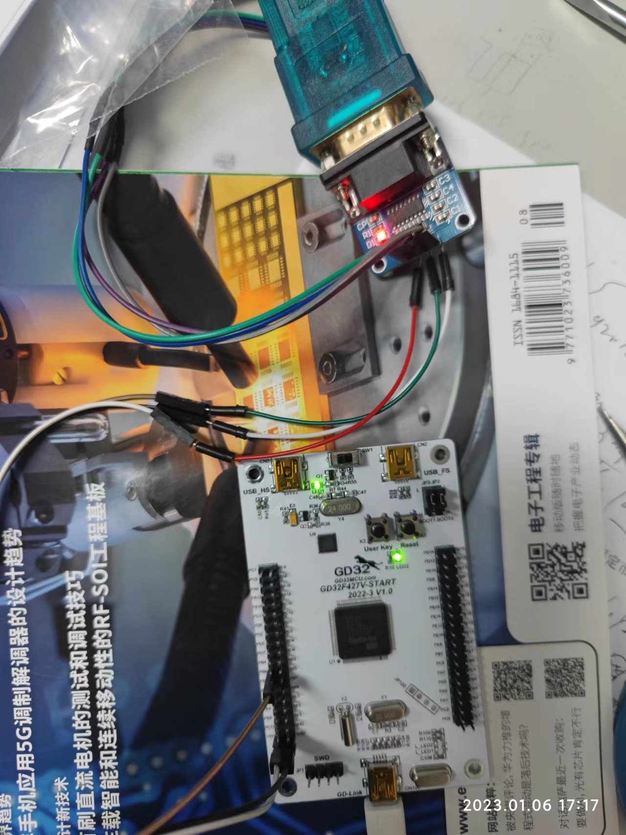
GD32F4系列MCU采用Arm® Cortex®-M4内核可支持算法复杂度更高的嵌入式应用,具备更快速的实时处理能力,很幸运能够有机会试用兆易公司的GD32F427V-START开发板。本次使用中,我将使用开发板测试之前使用过的DFT计算,采用定时器计算完成运算所用的时间,通过串口显示运算完成的时间。
软件环境
- 编程环境
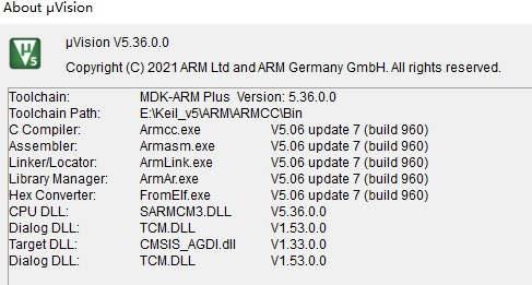
keil-MDK 5.36(Windows10)
串口工具 参考资料
设计说明
主要是利用GD32F427这个测试板,将之前在STM32F1系列上的一些运算搬移到到这个上面来通过模拟的数据量(本次测试没有经过实际的采样,利用已知的数据进行测试),进行DFT运算,通过1组数据运算和60组数据的运算来评估一下运算的时间,从而验证在实际运行中能满足产品的计算要求。
硬件需求分析
本次用到的硬件有TIMER1,USART0,GPIO等硬件资源。
- TIMER1 计算运算的时间。
USART0 波特率9600,发送显示计算时间
代码
/////////////////////////////////////////////////////////////
include "gd32f4xx.h"
include "gd32f427v_start.h"
include "systick.h"
include "stdio.h"
include  "math.h"
include  "stdint.h"
//数据类型定义
typedef unsigned char  boolen;
typedef unsigned char  u8;                    /* Unsigned  8 bit quantity                           */
typedef signed   char  s8;                    /* Signed    8 bit quantity                           */
typedef unsigned short u16;                   /* Unsigned 16 bit quantity                           */
typedef signed   short s16;                   /* Signed   16 bit quantity                           */
typedef unsigned long  u32;                   /* Unsigned 32 bit quantity                           */
typedef signed   long  s32;                   /* Signed   32 bit quantity                           */
typedef float          f32;                   /* Signed   32 bit quantity                           */

extern u8 times;
u16 sample_date[32][6];


void rcu_set(void)
{
  rcu_periph_clock_enable(RCU_GPIOB);
  rcu_periph_clock_enable(RCU_GPIOC);
  rcu_periph_clock_enable(RCU_TIMER1);
  rcu_periph_clock_enable(RCU_USART0);
}
//usart0设置
void usart0_set(void)
{
  /* USART configure */
  usart_deinit(USART0);
  usart_baudrate_set(USART0, 9600U);
  usart_receive_config(USART0, USART_RECEIVE_ENABLE);
  usart_transmit_config(USART0, USART_TRANSMIT_ENABLE);

  usart_enable(USART0);
}
//timer1设置(作为计时器用,查看计算时间,评估计算速度,1cnt = 0.001ms)
void timer1_set(void)
{
  timer_parameter_struct timer_initpara;
  /* TIMER1  configuration */
  timer_deinit(TIMER1);
  timer_initpara.prescaler         = 99;
  timer_initpara.alignedmode       = TIMER_COUNTER_EDGE;
  timer_initpara.counterdirection  = TIMER_COUNTER_UP;
  timer_initpara.period            = 1000000;   //计数值
  timer_initpara.clockdivision     = TIMER_CKDIV_DIV1;
  timer_initpara.repetitioncounter = 0; //
  timer_auto_reload_shadow_enable(TIMER1);//
  timer_init(TIMER1,&timer_initpara);
}
void gpio_init()
{
  /* configure LED2 GPIO port */
  gpio_mode_set(GPIOC, GPIO_MODE_OUTPUT, GPIO_PUPD_NONE, GPIO_PIN_6);
  gpio_output_options_set(GPIOC, GPIO_OTYPE_PP, GPIO_OSPEED_50MHZ, GPIO_PIN_6);
  //usart0串口设置PB6
  /* connect port to USARTx_Tx */
  gpio_af_set(GPIOB, GPIO_AF_7, GPIO_PIN_6);
  /* connect port to USARTx_Rx */
  gpio_af_set(GPIOB, GPIO_AF_7, GPIO_PIN_7);
  /* configure USART Tx as alternate function push-pull */
  gpio_mode_set(GPIOB, GPIO_MODE_AF, GPIO_PUPD_PULLUP, GPIO_PIN_6);
  gpio_output_options_set(GPIOB, GPIO_OTYPE_PP, GPIO_OSPEED_50MHZ, GPIO_PIN_6);
  /* configure USART Rx as alternate function push-pull */
  gpio_mode_set(GPIOB, GPIO_MODE_AF, GPIO_PUPD_PULLUP, GPIO_PIN_7);
  gpio_output_options_set(GPIOB, GPIO_OTYPE_PP, GPIO_OSPEED_50MHZ, GPIO_PIN_7);
}
int main(void)
{
  uint32_t cnt1_timer = 0;
  uint32_t cnt2_timer = 0;
  uint32_t cnt_timer  = 0;
  u8 i = 0;
  SystemInit();
  /* configure systick */
  systick_config();
  rcu_set();
  gpio_init();
  usart0_set();
  timer1_set();
  timer_enable(TIMER1);
  advalue();
  while(1) {
      /* turn on LED2*/
      gpio_bit_set(GPIOC, GPIO_PIN_6);
      /*AD sample */
      timer_counter_value_config(TIMER1,0);
      fft(addate);
      cnt_timer = timer_counter_read(TIMER1);
      printf("Dft-time1: %ld",cnt_timer);
      delay_1ms(1000);
      /*AD sample */
      timer_counter_value_config(TIMER1,0);
      for(i = 0; i <64; i++)
      {
         fft(addate);
      }
      cnt_timer = timer_counter_read(TIMER1);
      printf("Dft-time64: %ld",cnt_timer);
      /*AD count*/
      delay_1ms(1000);
      /* turn off LED2 */
      gpio_bit_reset(GPIOC, GPIO_PIN_6);
  }
}
计算结果以及分析
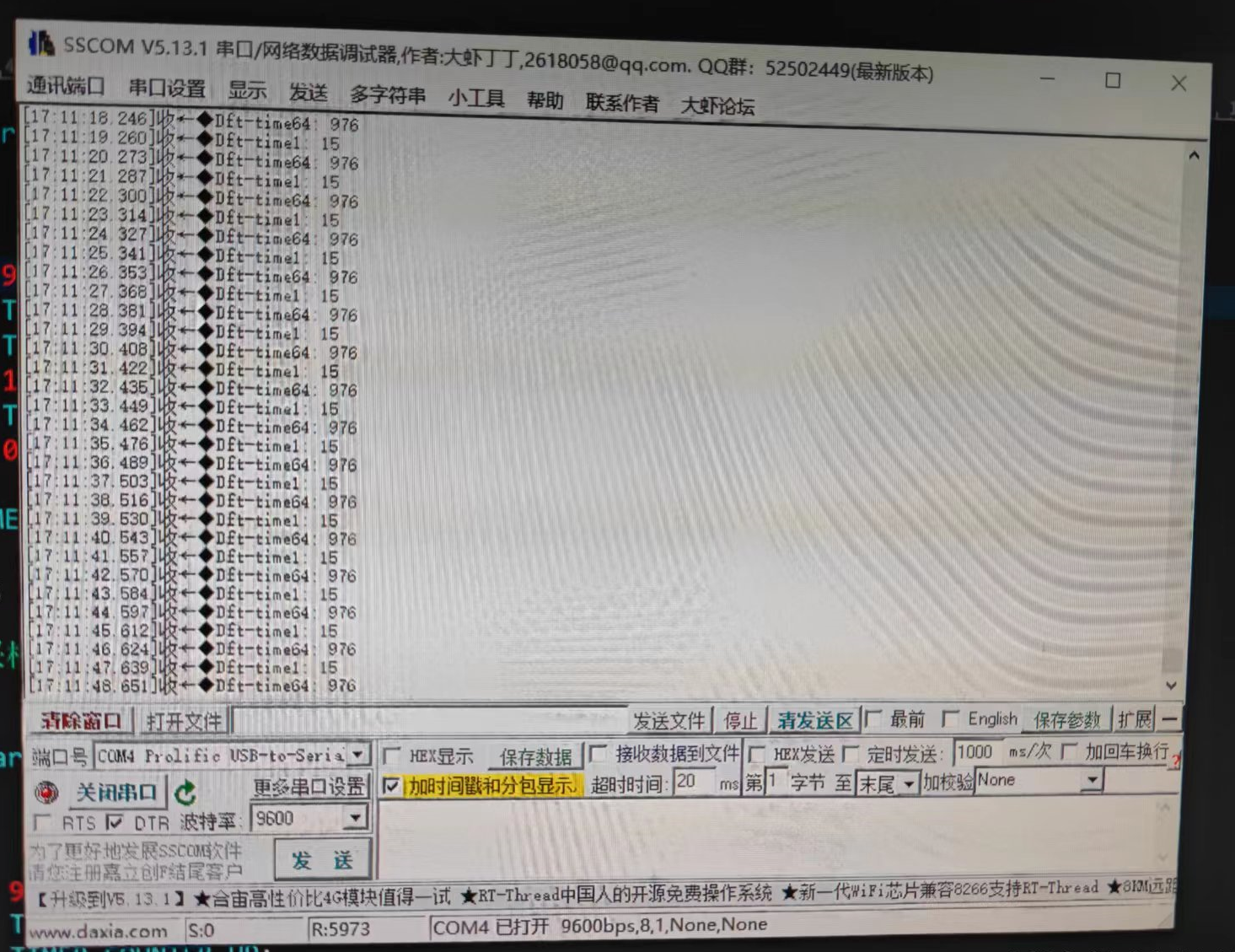
通过串口发送数据我们发现
单次运算计数为: 15
64次运算计数为: 976
每个计数单位的时间为0.001ms
单次运算时间为: 0.015ms
64次运算时间为: 0.976ms
可以看出,我们计算64组数据的时间不到1ms那么也就意味着我们可以同时监测更多的通道。
我们电力上的交流信号频率为50Hz,周期为20ms,在单一周期内可以完全计算出本次周波的幅值大小,并留出进行相关的记录和分析的充足时间。
总结
通过本次测试,GD32F427芯片能够满足实时采样计算的需求,主频能达到200MHz,相比之前用的STM32F1系列单片机,综合性能上有很大提高。比较适合做一些实时监测的产品。在当前形势下,国产arm芯片肯定是设计中的首选,在满足需求的前提下,我们优先选择国产,这样大概率能阻挡芯片缺货的风险。希望在今后的设计生产中早日批量使用GD产品,在批量生产中去验证产品的稳定性。感谢极数小姐姐在此次活动的帮助,由于本人水平有限,本文有错误和欠妥之处望大家批评指正,不吝赐教。


