Fab Academy,源自麻省理工学院的先进教育项目,致力于培养具有全球视野的创新者和制造者。通过密集学习和实践,学生们掌握了从基础到高级的制造技术,学习了如何将创意转化为现实。今天,小编将给大家带来其中一位Fab Academy毕业生 Kawi 的结项项目,一探他是如何将学习成果转化为令人瞩目的创新作品。
项目创作背景
当你盯着钟表上的时针看,它似乎移动得非常缓慢,就像时间在缓慢地流逝...非常缓慢。但是,当你瞥一眼秒针时,是否感觉时间实际上在加速——而且速度很快?这个作品意义在于鼓励每个人思考我们如何体验时间。根据我们选择观察的角度,时间可以以不同的方式影响我们。我希望人们能够欣赏到时间的价值,它总是在我们不知情时溜走。我们应该珍惜每一个时刻,尽情地生活。
当你离单指针时钟一米远时,指针代表时针;当你靠近至80厘米时,指针代表分针;当你靠近至60厘米时,指针代表秒针;当你更近时,指针会以最快的速度旋转。
项目草图与初步外观 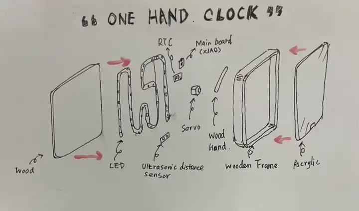
项目内容与规划
项目内容:
设计和构建一个时钟设备,该设备根据用户到设备的距离来更改显示的时间单位(小时、分钟、秒、十分之一秒)。此外,时钟还集成了 LED 照明功能,其中灯光的闪烁频率随着指针移动的速度加快一起加快。
项目规划:
| 步骤 | 内容描述 | 完成情况 |
|---|---|---|
| 1 | 要求与规划 | 完成 |
| 2 | 材料采购 | 完成 |
| 3 | 电路与机械设计 | 完成 |
| 4 | 软件开发与测试 | 完成 |
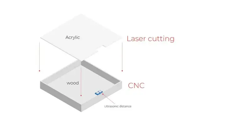
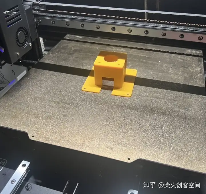
| 5 | 结构件生产(包括CNC切割、激光切割和3D打印) | 完成 |
| 6 | 硬件组装和调试 | 完成 |
| 7 | 制作视频和PPT介绍项目 | 完成 |
所需材料
根据草图,整理了项目所需的材料,并将它们分为两类:一类是电子的,另一类是外观设计。
电子材料:
| 数量 | 描述 | 价格 |
|---|---|---|
| 1 | Seeed Studio XIAO ESP32S3 Sense | 13.99$ |
| 1 | Steper moto | 1.99$ |
| 1 | Steper moto driver | 1$ |
| 1 | RTC | 7.06$ |
| 1 | Ultrasonic distance sensor | 3.18$ |
| 4 | Neo pixel - ws2812B | 4$ |
结构件与外壳
| 数量 | 描述 | 价格 |
|---|---|---|
| 1 | 底板 | 约5$ |
| 1 | 时钟指针 | 约1$ |
| 1 | 时钟的框架 | 约5$ |
| 1 | 时钟表面 | 6.46$ |
电路和机械设计
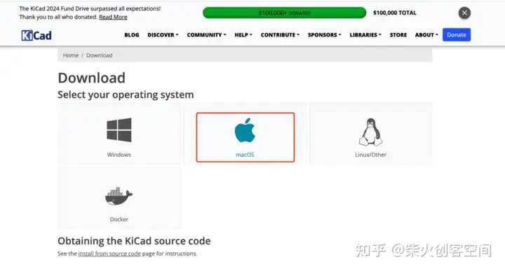
本项目选择KiCad作为电路板设计工具

KiCad 是一款用于印刷电路板设计的免费软件,最初由法国人 Jean-Pierre Charras 于 1992 年推出,现在由 KiCad 开发团队维护。KiCad 目前支持 23 种语言版本,包括英语、法语、德语、曼哈顿语、中文和芬兰语。
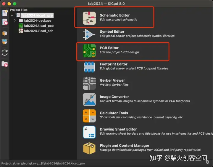
下载KiCad:
原理图编辑器和PCB编辑器是本项目需要使用的两个接口。
首先,我们安装fab的库,这是下载库的链接:
https://gitlab.fabcloud.org/pub/libraries/electronics/kicad
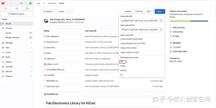
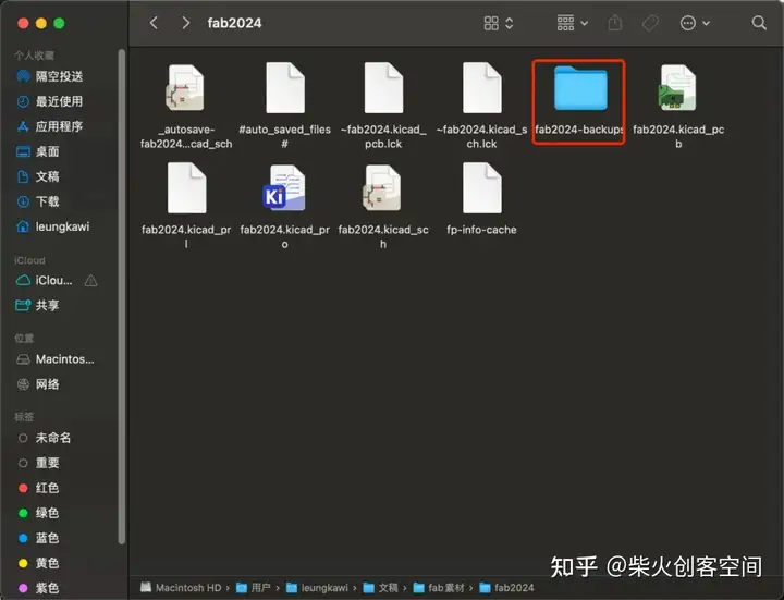
下载zip文件后解压文件:
然后在原理图编辑器中安装:
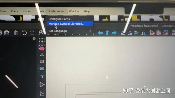
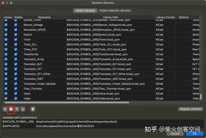
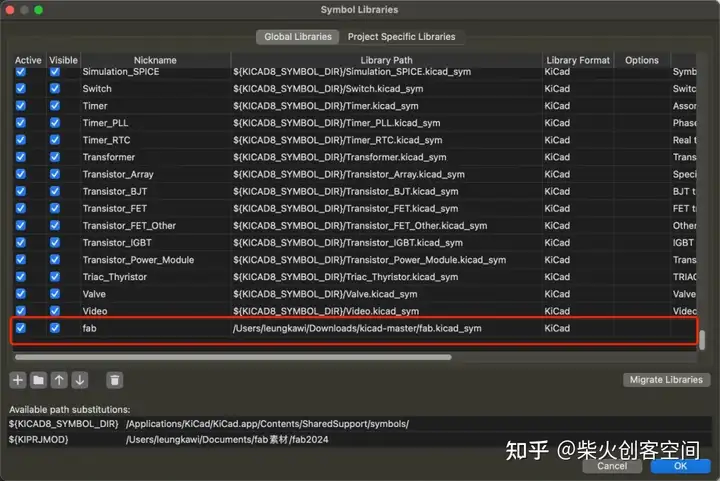
如果安装成功,它会在原理图库中显示:
原理图
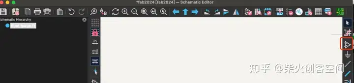
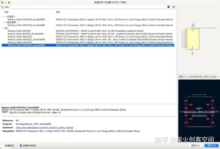
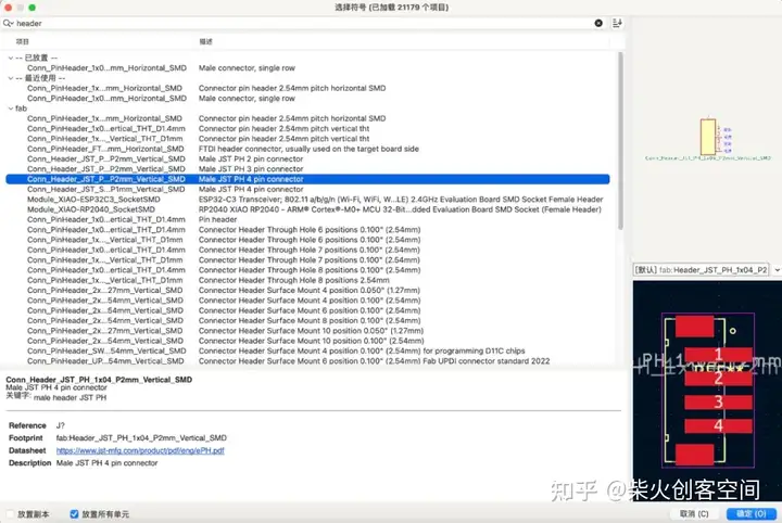
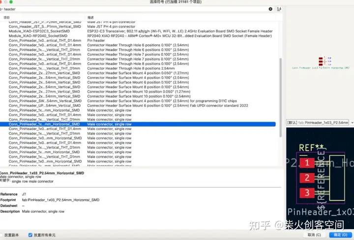
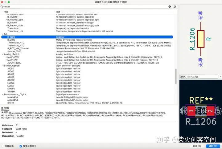
然后开始画电路板的原理图。打开软件,首先从这个位置找到需要使用的模块和相应的组件。
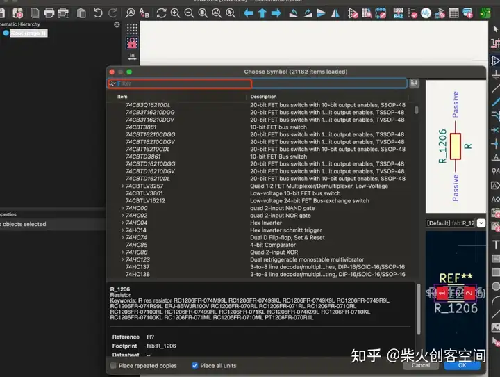
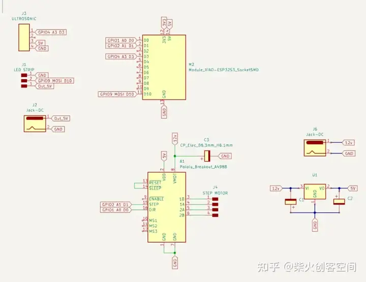
放置基本模块和组件后,如下所示:
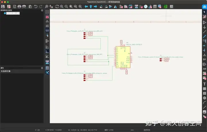
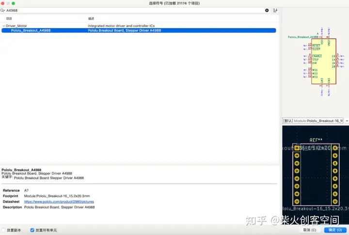
一开始我没有意识到需要驱动步进电机才能工作,所以我又增加了一个步进电机模块。
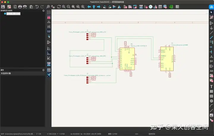
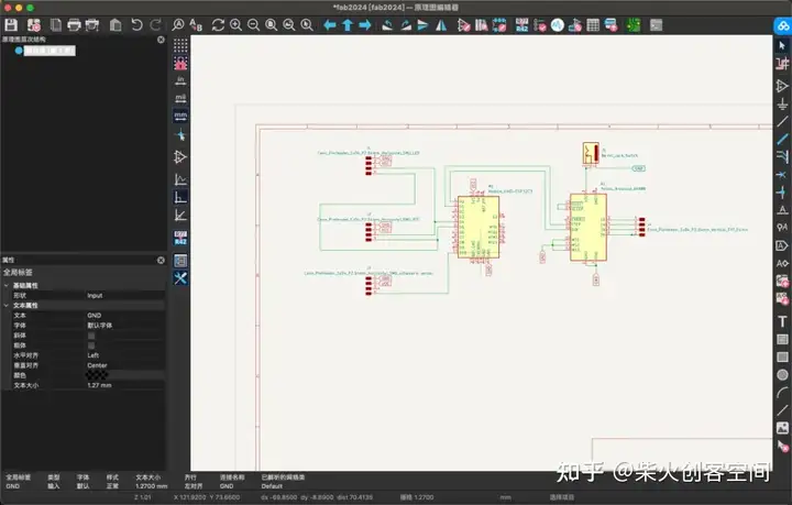
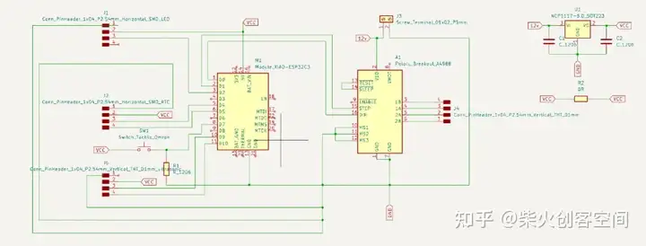
然后我根据每个模块的数据表将每个引脚连接到相应的位置。
PCB板图纸
然后我切换到PCB编辑器 打开PCB编辑器后,会出现一个窗口,提示您是否要从原理图更新到PCB。然后你可以看到所有的模块和组件都出现在界面中,你可以找到一些蓝色的细线将它们连接在一起。这些线路表示它们需要通过电路连接。
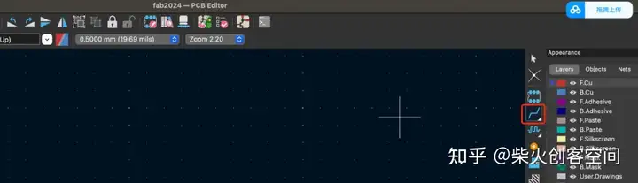
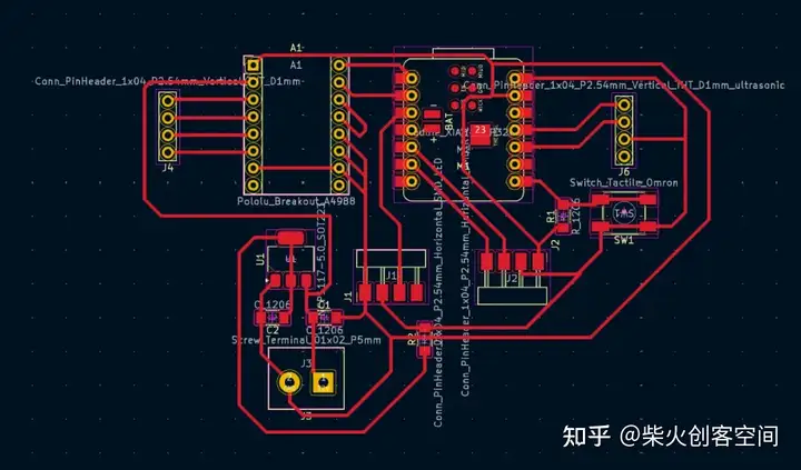
然后你需要使用这个工具连接所有需要用电路连接的引脚。
这一步需要很大的耐心。您需要尝试各种连接方法来防止电路重叠。这一步需要花了很长时间。在我的导师萨尔曼的帮助下,我终于完成了它:
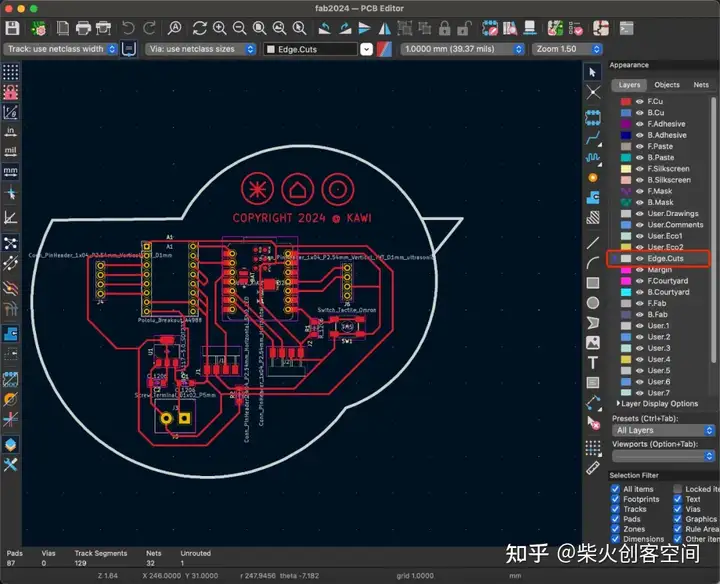
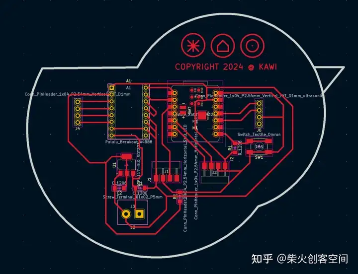
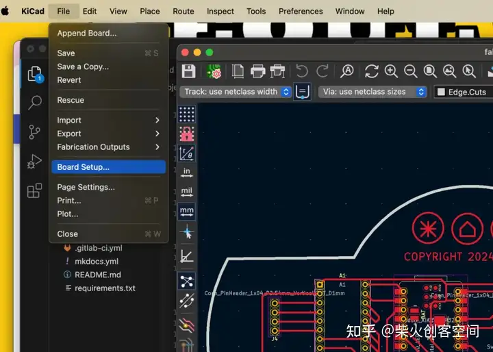
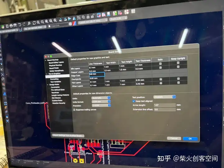
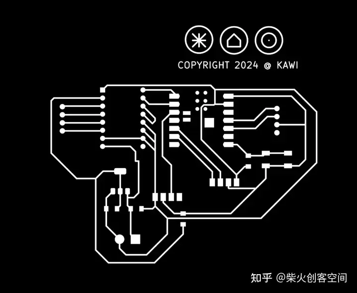
最后一步是画出整个PCB板的轮廓.有趣的是,我觉得我画的PCB板看起来像一只鸟,所以我为这块PCB板画了一只鸟的轮廓。请注意,在绘制轮廓时,需要切换到 edge.cut 模式,然后开始绘制。
完成电路图的绘制后, 下一步是切割PCB板。
在切割之前,我们需要了解G代码文件
CNC 机床的操作依赖于“G 代码”,并且有多种方法可用于生成此 G 代码。
G代码(也称为RS-274)是使用最广泛的计算机数控(CNC)和3D打印编程语言。它主要用于控制自动化机床的计算机辅助制造,以及 3D 打印机切片机应用。G代表几何形状。G-code 有许多变体。
G 代码指令提供给机器控制器(工业计算机),告诉电机移动的位置、移动速度和路径。两种最常见的情况是,在机床(如车床或铣床)中,切削刀具根据这些指令通过刀具路径移动,切掉材料以仅留下成品工件和/或未完成的工件精确定位在相对于刀具路径的三个维度的最多九个轴[1]中的任何一个,并且, 其中一个或两者都可以相对移动。同样的概念也延伸到非切削工具,如成型或抛光工具、照相绘图、增材方法(如3D打印)和测量仪器。
生成G代码
方法A:涉及利用“Mods CE”实用程序直接创建 G 代码,由于它们的无损分辨率质量,因此需要使用 PNG 或 SVG 图像;
方法B:可以将 Gerber 文件输入到数控机床的相应软件中,以方便自动生成代码。
首先,我需要设置电路板
然后导出 Gerber 文件。打开网站:https://http://gerber2png.fablabkerala.in/
将gerber文件转换为PNG文件, 这是一个电路文件
钻孔文件:
大纲文件:

然后打开网站:https://http://modsproject.org/?program=programs/machines/G-code/mill%202D%20PCB,将PNG文件转换为G-code,将PNG图像导入Mods CE中,设置参数如下图所示。您需要调整这两个部分的参数。
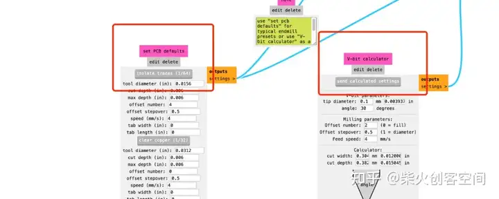
单击路径末尾的“计算”。整个过程看起来像如图:
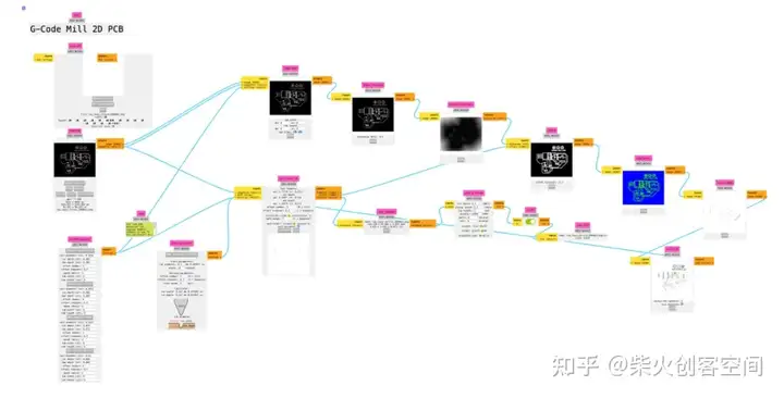
然后得到“nc”文件
nc文件为G代码文件。
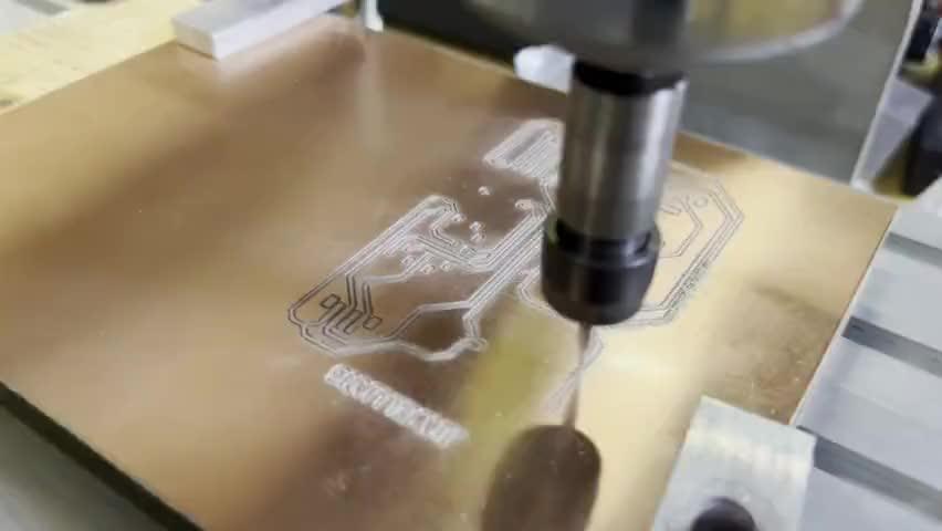
制造PCB板
准备好文件后,我可以开始切割PCB

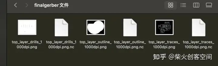
左边是0.4mm V型钻头,右边是0.8mm钻头。一共有三个切割文件:
1、 top\\\\_layer\\\\_drills\\\\_1000dpi.png.nc 使用 0.4mm V 位。
2、top\\\\_layer\\\\_outline\\\\_1000dpi.png.nc 和 top\\\\_layer\\\\_traces\\\\_1000dpi.png.nc
使用 0.8 毫米钻头。
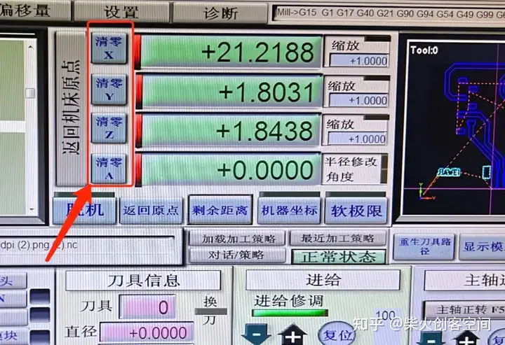
然后需要设置刀头的原点,并使用此工具将刀头移动到加工区域的角落,以确保不超过铜板的面积。
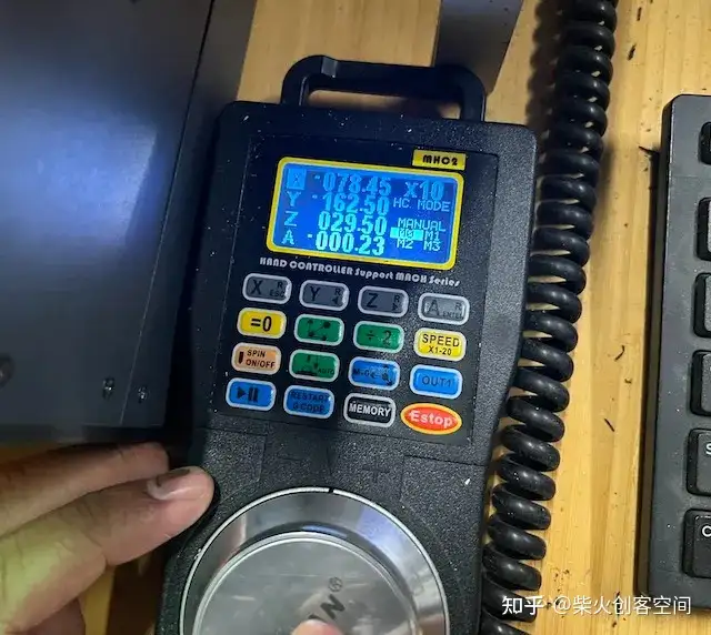

然后清除 X 轴和 Y 轴并保留 Z 轴
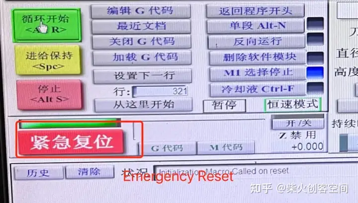
测试软件界面按钮是否可以控制设备的操作:点击 ”紧急复位“
坐标已清除:
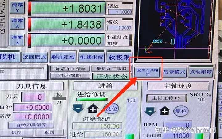
重新生成刀具路径:
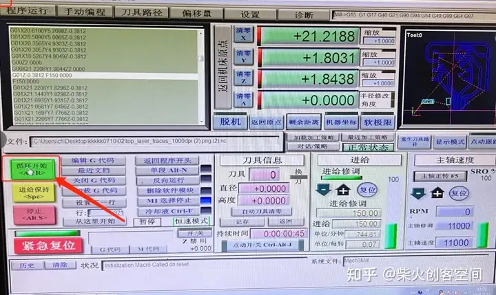
单击“开始”
剪切电路板的轮廓 导入帧文件,与剪切跟踪文件的操作相同
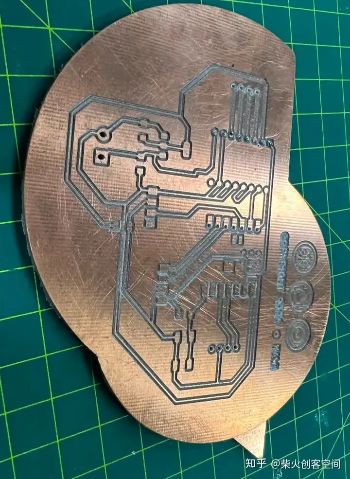
在这里,我们进入到最后切割完的电路板:
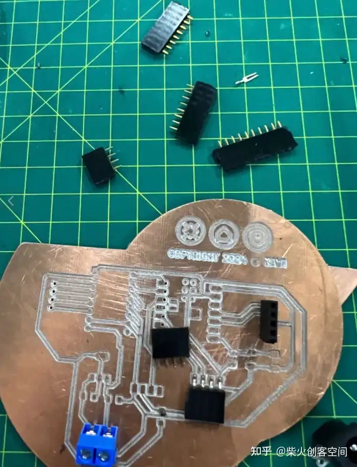
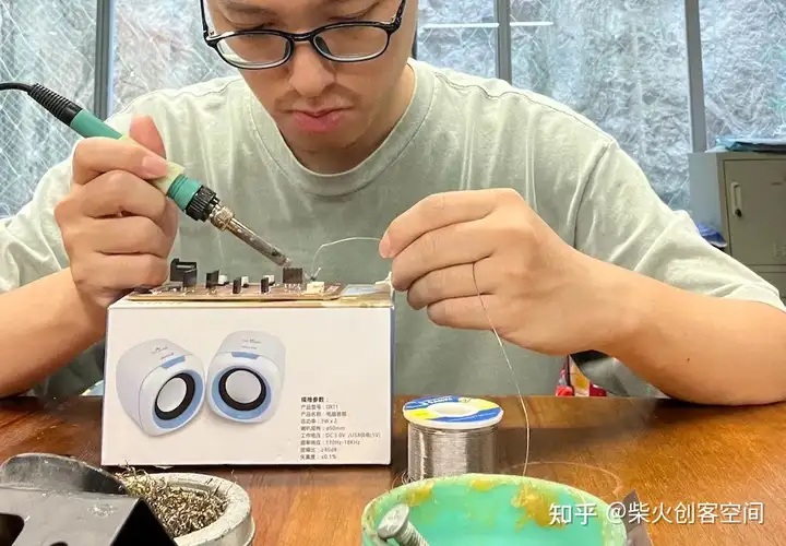
PCB焊接
我们首先准备必要的电子元件:
完成后,我们需要用万用表来检测电路中是否有短路
如下图所示,转动中间旋钮指向“Ω”,然后单击蓝色按钮切换模式。如果你看到信号的符号,你就可以开始测试了。让两个红色和黑色的头相互接触。会发出嗡嗡声,表示电路已连接。
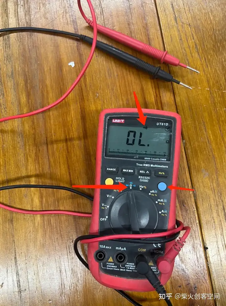
测试电路后,未发现异常,电路焊接完成。
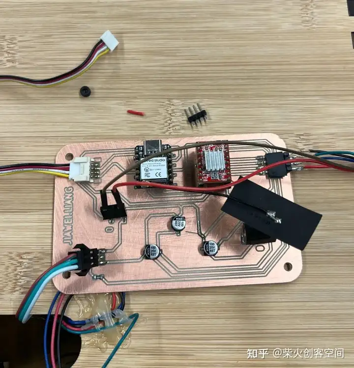
PCB测试
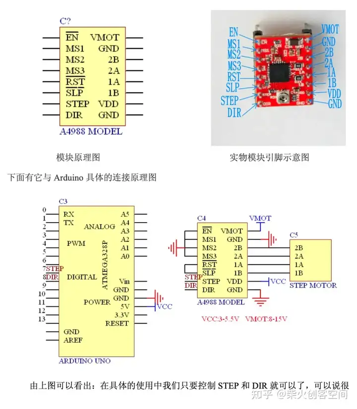
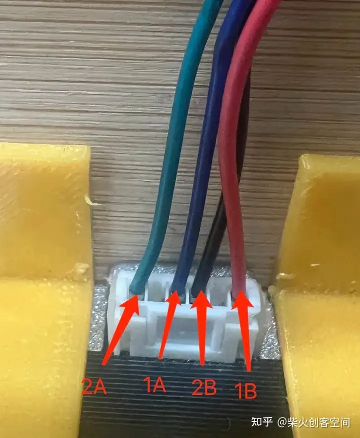
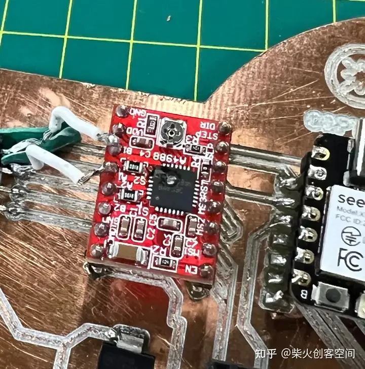
老师说,步进电机的负载会比较大,这部分可以先测试一下。因此,我将公引脚焊接到步进电机的 4 个接口上,并按照电机驱动器说明将它们连接到 PCB 板上(如下图所示)。
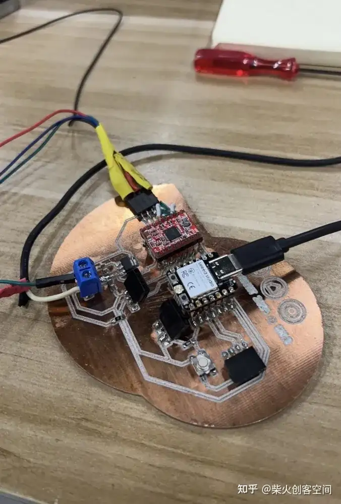
我准备好了之后,打开电源,发现电机动了一下,然后停了下来,电机驱动芯片还在冒烟。我立即断开电源,发现芯片已经烧毁了。
检查发现以下错误:1、步进电机驱动器没有散热片;2、电机四条线路连接顺序错误; 导致电路短路或错误,导致芯片过热烧坏。
所以我需要再次制作PCB
从原理图开始。
在此之前,导师建议我们可以先用条带做实验测试,然后再制造PCB板。
我开始使用面包板来测试电机如何正常工作
同时,我还重组了原理图

重新焊接:
测试完成后,发现有一种不需要使用RTC模块的新方法,所以整个电路也被修改了,这块板子不能再使用了。到目前为止,许多PCB板都被牺牲了。以下是他们的收藏展示, 这些PCB板真的花了我太多时间制作。 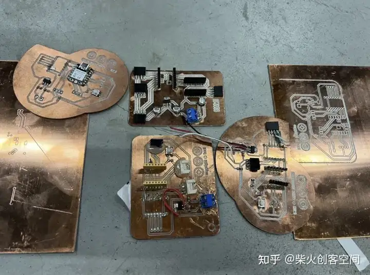
接下来,我需要将这个可行的演示集成到PCB板中。
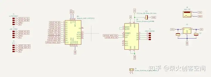
1、 如图以下是我将使用的组件
根据演示接线方法连接所有引脚,得到最终原理图
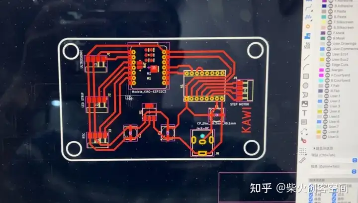
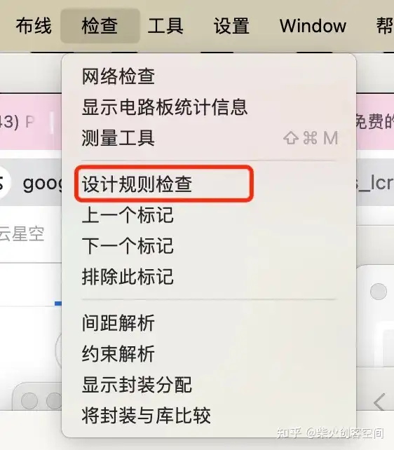
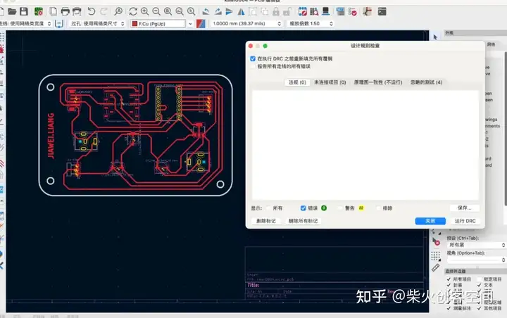
切换到PCB板设计,并将所有提示的连接与实际电路连接。我们得到下面的电路图,然后我们使用菜单栏中的“检查-设计规则检查”来测试PCB板是否有问题。
然后将Gerber转换为PNG & 将PNG转换为G代码
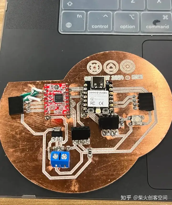
然后我终于可以重新开始制造了。
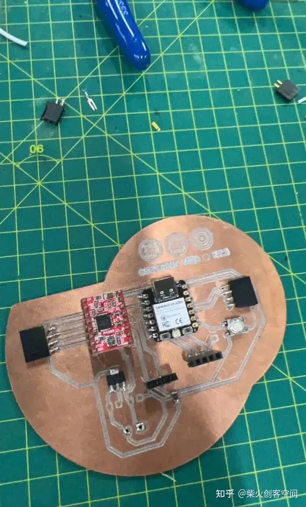
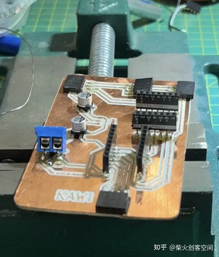
然后快速完成焊接:
编程
首先,我会说明在编写这段代码时需要实现的目标:
- 它需要在 ESP32 上运行;
- 使用Wi-Fi同步时间;
- 通过超声波传感器控制步进电机;
- 控制LED灯条的亮度。
转换为代码结构后,它包括以下结构
设置网络连接;
LED配置;
定时器配置;
实现多任务处理。
1.设置网络连接:
查找所有必需的库文件:
#include
#include
#include "Ultrasonic.h"
#include
#include "FastLED.h"
首先介绍Arduino核心库,WiFi库用于网络功能,超声波库用于读取超声波测距传感器,String用于字符串处理,FastLED用于控制LED灯带。
Wi-Fi 设置
const char *ssid = "x.factory";             // Wi-Fi SSID
const char *password = "make0314";          // Wi-Fi 密码
此处设置了用于连接到 Wi-Fi 网络的 SSID 和密码。请注意,这里需要 2.4G 网络。如果没有,则需要提前在网络设置中设置。
2. LED配置
LED灯条配置
#define NUM_LEDS 100
#define LED_DT 9
#define LED_TYPE WS2812
#define COLOR_ORDER GRB
此代码定义了使用的 LED 数量,我在这里设置了 100 盏灯 ,连接到 ESP32 的数据引脚(我定义 GPIO9)、LED 类型和颜色序列。
LED亮度和颜色配置
uint8_t max_bright = 128;
CRGB leds[NUM_LEDS];
CRGB myRGBcolor(50,50,50);
设置 LED 的最大亮度(调试后,这里我设置亮度 128)并定义一个 CRGB 阵列来控制 LED 灯条的每个 LED。还定义了颜色变量 myRGBcolor。
其他硬件配置
Ultrasonic ultrasonic*(4);
const int dirPin = 1;
const int stepPin = 2;
...
初始化步进电机的超声波传感器、方向和步进引脚。
3.定时器配置:
与时间相关的定义和变量
#define NTP1 "ntp1.aliyun.com"
...
String minute;
String second;
String hour;
定义 NTP 服务器地址和用于存储时间的字符串变量。
4.实现多任务处理:
多任务处理功能
xTaskOne
xTaskTwo
这两个函数是 FreeRTOS 任务,分别用于循环测量距离和控制 LED 灯带的亮度。
5.Setup 函数:
void setup() {
  ...
  WiFi.begin(ssid, password);
  ...
  configTime(8 * 3600, 0, NTP1, NTP2, NTP3);
  ...
  xTaskCreate(...);
}
在设置功能中,初始化串口,设置步进电机控制引脚,连接Wi-Fi网络,获取网络时间,创建前面描述的任务。
6.其他功能:
loop 函数:
此功能包括时间同步和根据超声波传感器读数控制步进电机的旋转,以模拟时钟时针、分针和秒针的运动。
onestep用于步进电机的一步操作。fast用于将步进电机快速旋转一整步。
getCurrentAngle\\\\_F和getCurrentAngle\\\\_S用于计算步进电机旋转的角度。
setClock 用于读取网络时间和更新时间变量。
经过多次测试和集成,最终的代码如下所示
#include
#include
#include "Ultrasonic.h"
#include
#include "FastLED.h"

//wifi config
const char *ssid = "x.factory";             // WIFI account
const char *password = "make0314";         // WIFI password

#define USE_MULTOCRE 0
#define NUM_LEDS 100            // set the num of led
#define LED_DT 9                // LED pin
#define LED_TYPE WS2812         // LED Light Strip Model
#define COLOR_ORDER GRB

uint8_t max_bright = 128;       // LED max bright

CRGB leds[NUM_LEDS];

//CRGB ColorName方法定义颜色
CRGB myRGBcolor(50,50,50);   // myRGBcolor(rValue,gValue,bValue)
                            // rValue: 0 - 255
                            // gValue: 0 - 255
                            // bValue: 0 - 255

Ultrasonic ultrasonic(4);
const int dirPin = 1;  // dir pin
const int stepPin = 2; // step pin
int num = 0;
const int STEPS_PER_REV = 1;
const float stepAngle = 0.9; // Step angle of stepper motor
const int microstepping = 1; // 1 = full step
long stepCount_S = 0;  // num of step fow slow

long stepCount_F = 0;  // num of step fow fast
long RangeInCentimeters = 1000;

int remember_min;  //rec min
int remember_sec;  // rec sec
int remember_hour; // rec hour

// Time info
#define NTP1 "ntp1.aliyun.com"
#define NTP2 "ntp2.aliyun.com"
#define NTP3 "ntp3.aliyun.com"


String minute;
String second;
String hour;

/*
Task one
  This function continuously measures the distance using an ultrasonic sensor,
  calculates the average of three measurements, and then prints the average distance.
*/
void xTaskOne(void *xTask1){

  int rangeMeasurements[3]; // Storage of three measurements
  int sum = 0; // For totalizing measured values

  while (1) {
    for (int i = 0; i < 3; i++) {  // Perform three measurements
      rangeMeasurements[i] = ultrasonic.MeasureInCentimeters(); // Get the distance in centimeters from the ultrasonic sensor
      sum += rangeMeasurements[i]; // Add the current measurement to the sum
      delay(250);
    }

    // Calculation of the average value
    int averageRange = sum / 3;
    RangeInCentimeters = averageRange;

    sum = 0;
    delay(500);
  }
  vTaskDelete(NULL);
}

/*
Task two
  This function is responsible for controlling the brightness of an LED strip.
*/
void xTaskTwo(void *xTask2){

  while (1) {
    // increase brightness
    for (double i = 20;i<150;i+=0.5){
      FastLED.setBrightness(i);
      myRGBcolor.r = 50;
      myRGBcolor.b = 50;
      myRGBcolor.g = 50;
      fill_solid(leds, NUM_LEDS, myRGBcolor);
      FastLED.show();
      delay(10);
    }
    // Reduced brightness
    for (double i = 150;i>20;i-=0.5){
      FastLED.setBrightness(i);
      myRGBcolor.r = 50;
      myRGBcolor.b = 50;
      myRGBcolor.g = 50;
      fill_solid(leds, NUM_LEDS, myRGBcolor);
      FastLED.show();
      delay(10);
    }
  }
  vTaskDelete(NULL);
}

void setup() {
  // put your setup code here, to run once:
  Serial.begin(115200);
  delay(500);

  // Set the pin modes for the stepper motor control pins
  pinMode(stepPin,OUTPUT);
  pinMode(dirPin,OUTPUT);

  // Set WiFi to station mode and attempt to connect to the specified network
  WiFi.mode(WIFI_STA);
  WiFi.begin(ssid, password);

  // Set WiFi to station mode and attempt to connect to the specified network
  LEDS.addLeds            LED_DT, COLOR_ORDER>(leds, NUM_LEDS);

  // Set the brightness of the LED strip to the maximum value
  FastLED.setBrightness(max_bright);

  // Wait for the WiFi connection to be established
  while (WiFi.status() != WL_CONNECTED)
  {
    delay(500);
    Serial.print(".");
  }
  Serial.println("WiFi connected!");
  configTime(8 * 3600, 0, NTP1, NTP2, NTP3);


#if !USE_MULTCORE
  // Create task one with a specified name, stack size, priority, and no parameters
  xTaskCreate(
    xTaskOne,/* Task function. */
    "TaskOne",/* String with name of task. */
    4096,/* Stack size in bytes.*/
    NULL,/* parameter passed as input of the task */
    1,/* priority of the task.(configMAx PRIORITIES - 1 being the highest, and @ being the lowest.) */
    NULL);/* Task handle.*/


  // Create task two with a specified name, stack size, priority, and no parameters
  xTaskCreate(
    xTaskTwo,/* Task function.*/
    "TaskTwo",/* String with name of task. */
    4096,/* Stack size in bytes.*/
    NULL,/* parameter passed as input of the task */
    2,/* priority of the task.(configMax PRIORITIES - 1 being the highest, and  being the lowest.) */
    NULL);  /* Task handle.*/

#else
  xTaskCreatepinnedToCore(xTaskOne,"TaskOne",4096,NULL,1,NULL,0);
  xTaskCreatepinnedToCore(xTaskTwo,"TaskTwo",4896,NULL,2,NULL,1);

#endif


}

void loop() {

  int current_angle;    // Variable to store the current angle of the actuator in 360 degree
  int getCurrentAngle; // Variable to store the total angle of the actuator

  if(RangeInCentimeters  > 300){
    setClock(); // Function to read the current time
    int num_hour = hour.toInt(); // Convert the current hour to an integer

    if(num_hour>12){
      num_hour = num_hour - 12; // Convert to 12-hour format if greater than 12
    }

    // Check if the current hour is different from the remembered hour
    if(num_hour != remember_hour){
      remember_hour = num_hour; // Update the remembered hour
      int target_angle = num_hour * 30; // Calculate the target angle based on the hour
      Serial.print("hour is, ");
      Serial.println(num_hour);
      getCurrentAngle = getCurrentAngle_S(); // Get the current angle
      current_angle = getCurrentAngle % 360; // Update the current angle, wrapping around at 360 degrees

      // Determine the direction to rotate and perform the rotation
      if(target_angle > current_angle){
        for(int i = 0; i < (target_angle - current_angle)/0.9; i++){
          onestep();
          delay(10);
        }
      }else{
        for(int i = 0; i < (target_angle + 360 - current_angle)/0.9; i++){
          onestep();
        }
      }
      // getCurrentAngle = getCurrentAngle_S();
      // current_angle = getCurrentAngle % 360;
      // Serial.print("current angle is ");
      // Serial.println(current_angle);
    }

  }
  else if(RangeInCentimeters  < 300 && RangeInCentimeters  > 50){ // Minutes logic
    remember_hour = 60;
    setClock();
    int num_min = minute.toInt();
    if(num_min != remember_min){
      remember_min = num_min;
      int target_angle = num_min * 6;
      Serial.print("min is, ");
      Serial.println(num_min);
      getCurrentAngle = getCurrentAngle_S();
      current_angle = getCurrentAngle % 360;

      if(target_angle > current_angle){
        for(int i = 0; i < (target_angle - current_angle)/0.9; i++){
          onestep();
          delay(10);
        }
      }else{
        for(int i = 0; i < (target_angle + 360 - current_angle)/0.9; i++){
          onestep();
        }
      }
    }
 } else{ // Seconds logic
  remember_min = 70;
  remember_hour = 60;
  setClock();
  int num_sec = second.toInt();

  if(num_sec != remember_sec){
    remember_sec = num_sec;
    int target_angle = num_sec * 6;
    Serial.print("sec is, ");
    Serial.println(num_sec);
    getCurrentAngle = getCurrentAngle_S();
    current_angle = getCurrentAngle % 360;

    if(target_angle > current_angle){
      for(int i = 0; i < (target_angle - current_angle)/0.9; i++){
        onestep();
        // Serial.print(i);
        delay(10);
      }
    }else{
      for(int i = 0; i < (target_angle + 360 - current_angle)/0.9; i++){
        onestep();
      }
    }
    getCurrentAngle = getCurrentAngle_S();
    current_angle = getCurrentAngle % 360;
    Serial.print("current angle is ");
    Serial.println(current_angle);
  }

 }


}

void onestep(){

  digitalWrite(dirPin,HIGH);
  digitalWrite(stepPin,HIGH);
  delayMicroseconds(1000);
  digitalWrite(stepPin,LOW);
  delayMicroseconds(1000);
  stepCount_S++; // update the num of step
  // delay(1000);
}
void fast(){
digitalWrite(dirPin,HIGH);

  for(int x = 0; x < STEPS_PER_REV ; x++) {
    digitalWrite(stepPin,HIGH);
    delayMicroseconds(1000);
    digitalWrite(stepPin,LOW);
    delayMicroseconds(1000);
    stepCount_F++;
  }

}


float getCurrentAngle_F() {
  return stepCount_F * (stepAngle / microstepping);
}
float getCurrentAngle_S() {
  return stepCount_S * (stepAngle / microstepping);
}


//time_t now;
void setClock()
{
  struct tm timeInfo;
  if (!getLocalTime(&timeInfo))
  {
    Serial.println("Failed to obtain time");
    return;
  }
  //Serial.print(asctime(&timeInfo));
  // String date = WDAY_NAMES[timeInfo.tm_wday];
  // Serial.println(date.c_str());
  // sprintf_P(buff1, PSTR("%04d-%02d-%02d %s"), timeInfo.tm_year + 1900, timeInfo.tm_mon + 1, timeInfo.tm_mday, WDAY_NAMES[timeInfo.tm_wday].c_str());
  // String shuju = String(timeInfo.tm_year + 1900);
  // shuju += "-";
  // // shuju += timeInfo.tm_mon + 1;
  // // shuju += "-";
  // shuju += timeInfo.tm_mday;
  // shuju += " ";
  // shuju += timeInfo.tm_hour;
  // shuju += ":";
  // shuju += timeInfo.tm_min;
  // shuju += ":";
  // shuju += timeInfo.tm_sec;
  // shuju += " ";
  // // shuju += WDAY_NAMES[timeInfo.tm_wday].c_str();
  // Serial.println(shuju.c_str());
  minute = timeInfo.tm_min;
  second = timeInfo.tm_sec;
  hour = timeInfo.tm_hour;
}
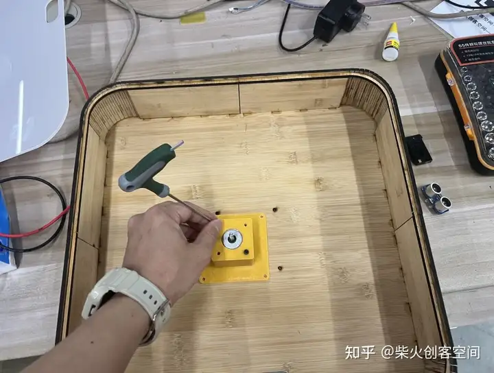
外观设计
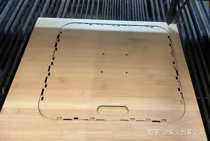
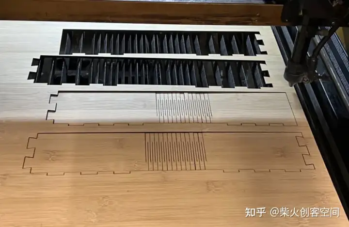
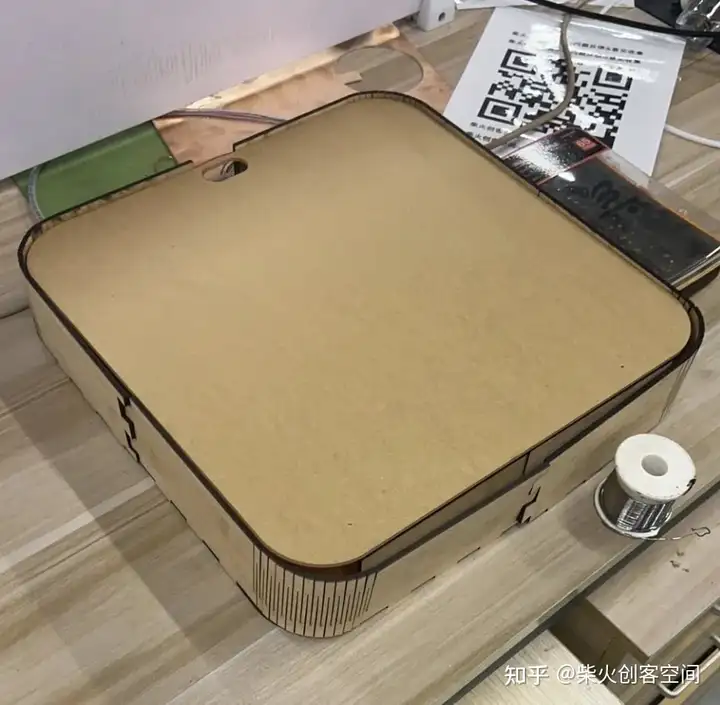
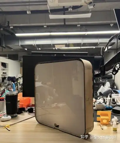
集成组装