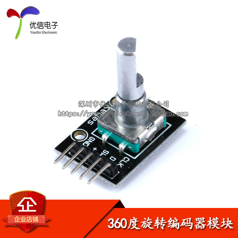
之前做过一个LED调光的项目(https://oshwhub.com/czx951002/ChargeablePWMDimmingLEDDriver),这次想拿XR806来实现,后续打算加入远程控制的功能。这个项目使用旋转编码器来调节LED的亮度,基本原理是MCU识别编码器的旋转方向和步数,调节PWM输出占空比,从而实现亮度调节。
旋转编码器如下图所示: 
识别其旋转方向和步数,要考虑消除抖动,否则会出现识别错误,导致系统不稳定,这和按键是类似的。具体原理可以参考这篇博客。
Github上有对应的Arduino库,注意它的开源协议是GNU GPL V3!本人曾经移植到STM32,现已移植到XR806,效果良好,源码链接。旋转编码器相关代码如下:
头文件re.h源码:
/*
 * Rotary encoder library for Arduino.
 * Port to XR806 by Zixun Chen.
 */

#ifndef _ROTARY_ENCODER_H_
#define _ROTARY_ENCODER_H_

#ifdef __cplusplus
extern "C" {
#endif

#include "main.h"

// 根据编码器的输出类型来选择是否定义RE_HALF_STEP
#define RE_HALF_STEP

// 旋转编码器通常外接上拉电阻,对应空闲电平是00B。如果外接电阻是下拉的,需要定义RE_PINS_PULL_DOWN
// #define RE_PINS_PULL_DOWN

#define DIR_NONE 0    // 尚无完整有效的步进
#define DIR_CW   0x10 // 顺时针步进
#define DIR_CCW  0x20 // 逆时针步进

typedef struct {
    // 定义编码器A端所连的GPIO引脚
    GPIO_Port GPIO_A;
    GPIO_Pin PIN_A;
    // 定义编码器B端所连的GPIO引脚
    GPIO_Port GPIO_B;
    GPIO_Pin PIN_B;
    uint8_t RetVal; // 保存返回值
    uint8_t State; // 内部变量,保存状态机状态
} REHandle_t;

void RotaryEncoderInit(REHandle_t *REVal); // 初始化
void RotaryEncoderProcess(REHandle_t *REVal); // 读取步进

#ifdef __cplusplus
}
#endif

#endif // _ROTARY_ENCODER_H_
源文件re.c:
/* Rotary encoder handler for arduino.
 *
 * Copyright 2011 Ben Buxton. Licenced under the GNU GPL Version 3.
 * Contact: bb@cactii.net
 *
 * Port to XR806 by Zixun Chen.
 */

#include "re.h"

/*
 * The below state table has, for each state (row), the new state
 * to set based on the next encoder output. From left to right in,
 * the table, the encoder outputs are 00, 01, 10, 11, and the value
 * in that position is the new state to set.
 */

#define R_START 0x0

#ifdef RE_HALF_STEP
// Use the half-step state table (emits a code at 00 and 11)
#define R_CCW_BEGIN 0x1
#define R_CW_BEGIN 0x2
#define R_START_M 0x3
#define R_CW_BEGIN_M 0x4
#define R_CCW_BEGIN_M 0x5
const unsigned char ttable[6][4] = {
    // R_START (00)
    {R_START_M,           R_CW_BEGIN,    R_CCW_BEGIN,  R_START},
    // R_CCW_BEGIN
    {R_START_M | DIR_CCW, R_START,       R_CCW_BEGIN,  R_START},
    // R_CW_BEGIN
    {R_START_M | DIR_CW,  R_CW_BEGIN,    R_START,      R_START},
    // R_START_M (11)
    {R_START_M,           R_CCW_BEGIN_M, R_CW_BEGIN_M, R_START},
    // R_CW_BEGIN_M
    {R_START_M,           R_START_M,     R_CW_BEGIN_M, R_START | DIR_CW},
    // R_CCW_BEGIN_M
    {R_START_M,           R_CCW_BEGIN_M, R_START_M,    R_START | DIR_CCW},
};
#else
// Use the full-step state table (emits a code at 00 only)
#define R_CW_FINAL 0x1
#define R_CW_BEGIN 0x2
#define R_CW_NEXT 0x3
#define R_CCW_BEGIN 0x4
#define R_CCW_FINAL 0x5
#define R_CCW_NEXT 0x6

const unsigned char ttable[7][4] = {
  // R_START
  {R_START,    R_CW_BEGIN,  R_CCW_BEGIN, R_START},
  // R_CW_FINAL
  {R_CW_NEXT,  R_START,     R_CW_FINAL,  R_START | DIR_CW},
  // R_CW_BEGIN
  {R_CW_NEXT,  R_CW_BEGIN,  R_START,     R_START},
  // R_CW_NEXT
  {R_CW_NEXT,  R_CW_BEGIN,  R_CW_FINAL,  R_START},
  // R_CCW_BEGIN
  {R_CCW_NEXT, R_START,     R_CCW_BEGIN, R_START},
  // R_CCW_FINAL
  {R_CCW_NEXT, R_CCW_FINAL, R_START,     R_START | DIR_CCW},
  // R_CCW_NEXT
  {R_CCW_NEXT, R_CCW_FINAL, R_CCW_BEGIN, R_START},
};
#endif

static uint8_t ReadPinLevel(GPIO_Port GPIOx, GPIO_Pin PINy); // 内部函数,读取引脚电平

void RotaryEncoderInit(REHandle_t *REVal) {
    GPIO_InitParam GPIO_InitVal={0};
    // 初始化GPIO引脚
    GPIO_InitVal.driving=GPIO_DRIVING_LEVEL_1;
    GPIO_InitVal.mode=GPIOx_Pn_F0_INPUT;
    GPIO_InitVal.pull=GPIO_PULL_NONE;
    HAL_GPIO_Init(REVal->GPIO_A, REVal->PIN_A, &GPIO_InitVal);
    HAL_GPIO_Init(REVal->GPIO_B, REVal->PIN_B, &GPIO_InitVal);
    // 初始化状态机
    REVal->State=R_START;
}

void RotaryEncoderProcess(REHandle_t *REVal) {
    uint8_t pinstate;
    // 读取AB端电平
    pinstate=(ReadPinLevel(REVal->GPIO_B, REVal->PIN_B)<<1) |
              ReadPinLevel(REVal->GPIO_A, REVal->PIN_A);
    // 状态机操作
    REVal->State=ttable[REVal->State & 0xf][pinstate];
    // 返回编码器步进信息
    REVal->RetVal=REVal->State & 0x30;
}

static uint8_t ReadPinLevel(GPIO_Port GPIOx, GPIO_Pin PINy)
{
    GPIO_PinState RDPin;
    RDPin=HAL_GPIO_ReadPin(GPIOx, PINy);
    #ifdef RE_PINS_PULL_DOWN
    // 如果定义RE_PINS_PULL_DOWN,需要反转引脚电平
    if(GPIO_PIN_HIGH==RDPin) {
        return 0;
    } else {
        return 1;
    }
    #else // RE_PINS_PULL_DOWN
    if(GPIO_PIN_HIGH==RDPin) {
        return 1;
    } else {
        return 0;
    }
    #endif // RE_PINS_PULL_DOWN
}
编码器A端和B端分别连接PA12和PA13,使用板载LED即可,引脚是PA21,对应PWM\_CH2。开发环境基于FreeRTOS,参考相关教程即可,XR806 SDK在 ~/tools/目录下。在 ~/tools/xr806_sdk/project/demo/ 目录下新建 tryre 文件夹,并在其中添加源代码,makefile等文件,然后按照教程编译链接下载即可。主要代码如下:
头文件main.h:
#ifndef __MAIN_H
#define __MAIN_H

#ifdef __cplusplus
extern "C" {
#endif

// 需要包含的头文件
#include <stdio.h>
#include "driver/chip/hal_gpio.h"
#include "driver/chip/hal_pwm.h"
#include "re.h"
#include "FreeRTOS.h"
#include "task.h"

#ifdef __cplusplus
}
#endif

#endif /* __MAIN_H */
main.c:
#include "main.h"

// 定义编码器占用的GPIO引脚
static REHandle_t REVal={
    .GPIO_A=GPIO_PORT_A,
    .PIN_A=GPIO_PIN_12,
    .GPIO_B=GPIO_PORT_A,
    .PIN_B=GPIO_PIN_13
};
static const uint8_t STEPMAX=10, STEPMIN=0;
static uint8_t step=0; // 控制LED亮度等级
static void RotaryScan(void); // 编码器识别与处理
// PWM输出初始化
#define PWM_CHANNEL   PWM_GROUP1_CH2
#define PWM_MODE      PWM_CYCLE_MODE
#define PWM_GPIO_PORT GPIO_PORT_A
#define PWM_GPIO_PIN  GPIO_PIN_21
#define PWM_GPIO_MODE GPIOA_P21_F4_PWM2_ECT2
static int max_duty_ratio; // PWM计数上限
static void PWMCycleModeSet(void); // PWM重复输出模式初始化
static HAL_Status PWMDutyRatioSet(int val); // 设置PWM输出占空比
// FreeRTOS配置
#define TASK_RE_PRIO     1
#define TASK_RE_STK_SIZE 200
static TaskHandle_t TaskRE_Handler=NULL;
static void TaskCreation(void); // 创建任务
static void TaskRE(void *pvParameters); // 编码器识别任务

int main(void)
{
    printf("Rotary encoder & PWM demo.\r\n"); // 串口输出相关信息
    RotaryEncoderInit(&REVal); // 初始化编码器
    PWMCycleModeSet(); // 初始化PWM
    PWMDutyRatioSet(max_duty_ratio*step/STEPMAX); // 设置PWM输出占空比
    TaskCreation(); // 创建任务
    // 任务调度不需要用户指定
    return 0;
}

static void TaskCreation(void)
{
    BaseType_t xRet = NULL;
    taskENTER_CRITICAL();
    xRet = xTaskCreate((TaskFunction_t )TaskRE, (const char *)"TaskRE", (uint16_t)TASK_RE_STK_SIZE,
                       (void *)NULL, (UBaseType_t)TASK_RE_PRIO, (TaskHandle_t *)&TaskRE_Handler);
    if(pdPASS == xRet) {
        printf("TaskRE created!\r\n"); // 任务创建成功
    }
    taskEXIT_CRITICAL();
}

static void TaskRE(void *pvParameters)
{
    while (1) {
        RotaryScan(); // 识别编码器步进
        vTaskDelay(10); // 延迟10(ms)
    }
}

static void RotaryScan(void)
{
    RotaryEncoderProcess(&REVal); // 识别编码器步进
    if(DIR_CW == REVal.RetVal) { // 顺时针步进
        if(step<STEPMAX) {
            step++; // 增大亮度,上限是STEPMAX
            PWMDutyRatioSet(max_duty_ratio*step/STEPMAX);
            printf("%d  ", step);
        }
    } else if(DIR_CCW == REVal.RetVal) {
        if(step>STEPMIN) {
            step--; // 减小亮度,下限是STEPMIN
            PWMDutyRatioSet(max_duty_ratio*step/STEPMAX);
            printf("%d  ", step);
        }
    }
}

static void PWMCycleModeSet(void)
{
    // 初始化硬件所需变量声明
    GPIO_InitParam io_param = {0};
    HAL_Status status = HAL_ERROR;
    PWM_ClkParam clk_param = {0};
    PWM_ChInitParam ch_param = {0};
    // 配置GPIO复用,官方例程里面缺了这一部分
    io_param.driving = GPIO_DRIVING_LEVEL_1;
    io_param.mode = PWM_GPIO_MODE;
    io_param.pull = GPIO_PULL_NONE;
    HAL_GPIO_Init(PWM_GPIO_PORT, PWM_GPIO_PIN, &io_param);
    // 配置PWM时钟源
    clk_param.clk = PWM_CLK_HOSC;
    clk_param.div = PWM_SRC_CLK_DIV_1;
    status = HAL_PWM_GroupClkCfg(PWM_CHANNEL / 2, &clk_param);
    if (status != HAL_OK) {
        printf("%s(): %d, PWM group clk config error\n", __func__, __LINE__);
    }
    // 配置PWM模式,频率和极性
    ch_param.hz = 1000;
    ch_param.mode = PWM_MODE;
    ch_param.polarity = PWM_HIGHLEVE;
    max_duty_ratio = HAL_PWM_ChInit(PWM_CHANNEL, &ch_param);
    if (max_duty_ratio == -1) {
        printf("%s(): %d, PWM ch init error\n", __func__, __LINE__);
    }
    // 设置占空比
    status = HAL_PWM_ChSetDutyRatio(PWM_CHANNEL, max_duty_ratio / 2);
    if (status != HAL_OK) {
        printf("%s(): %d, PWM set duty ratio error\n", __func__, __LINE__);
    }
    // 使能通道
    status = HAL_PWM_EnableCh(PWM_CHANNEL, PWM_MODE, 1);
    if (status != HAL_OK) {
        printf("%s(): %d, PWM ch enable error\n", __func__, __LINE__);
    }
}

static HAL_Status PWMDutyRatioSet(int val)
{
    return HAL_PWM_ChSetDutyRatio(PWM_CHANNEL, val);
}
效果展示:
https://www.bilibili.com/video/BV1ou4y147Bg/?aid=916615411&cid=1283344916&page=null


