I/O使用
操作I/O是玩硬件的基础,我们可以用来控制开关量的设备,例如点灯、蜂鸣器、按键等等。详细的硬件的设计这里并不做解释,课参考单片机的学习资料,主要介绍程序撰写。
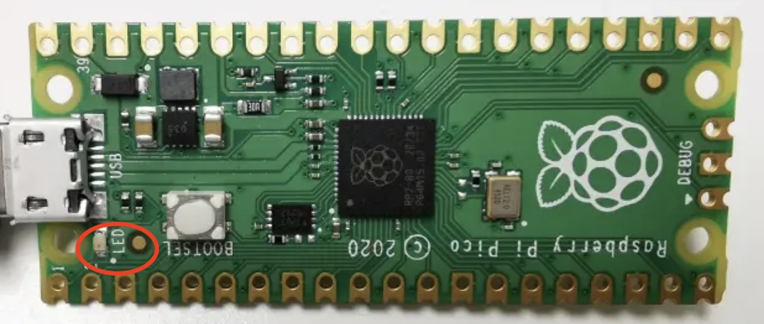
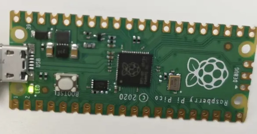
我们以点灯为例子看一下GPIO的使用,在核心板上就一偶一个LED:
在开始安装环境的时候阿chai提供的程序就是点灯的程序,接下来我们看看具体是如何操作的。
MicroPython版本
MicroPython中提供了点灯的接口,我们看一下程序:
# 调用pico的GPIO模块
from machine import Pin

# 设置GPIO的模式,案例中为输出模式
led = Pin(25, Pin.OUT)

# 输出高低电平
led.value(1)
led.value(0)
这个时候我们可以看到小灯是亮一下灭了。
C/C++版本
以下为运行程序:
#include "pico/stdlib.h"  //头文件

int main() {
    const uint LED_PIN = 25;  //设置IO口
    gpio_init(LED_PIN);  //初始化IO
    gpio_set_dir(LED_PIN, GPIO_OUT);  //设置IO口的模式
    while (true) {
        gpio_put(LED_PIN, 1);  //输出高电平
        sleep_ms(250);                 //延时250ms
        gpio_put(LED_PIN, 0);  //输出低电平
        sleep_ms(250);                 //延时250ms
    }
}
CMakeLists.txt:
add_executable(blink
        blink.c
        )

# Pull in our pico_stdlib which pulls in commonly used features
target_link_libraries(blink pico_stdlib)

# create map/bin/hex file etc.
pico_add_extra_outputs(blink)

# add url via pico_set_program_url
example_auto_set_url(blink)
UART
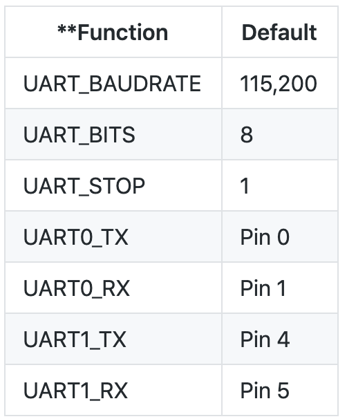
USART是一个全双工通用同步/异步串行收发模块,该接口是一个高度灵活的串行通信设备。USART收发模块一般分为三大部分:时钟发生器、数据发送器和接收器。控制寄存器为所有的模块共享。
MicroPython
from machine import Pin
from rp2 import PIO, StateMachine, asm_pio

UART_BAUD = 115200
PIN_BASE = 10
NUM_UARTS = 8


@asm_pio(sideset_init=PIO.OUT_HIGH, out_init=PIO.OUT_HIGH, out_shiftdir=PIO.SHIFT_RIGHT)
def uart_tx():
    # Block with TX deasserted until data available
    pull()
    # Initialise bit counter, assert start bit for 8 cycles
    set(x, 7)  .side(0)       [7]
    # Shift out 8 data bits, 8 execution cycles per bit
    label("bitloop")
    out(pins, 1)              [6]
    jmp(x_dec, "bitloop")
    # Assert stop bit for 8 cycles total (incl 1 for pull())
    nop()      .side(1)       [6]


# Now we add 8 UART TXs, on pins 10 to 17. Use the same baud rate for all of them.
uarts = []
for i in range(NUM_UARTS):
    sm = StateMachine(
        i, uart_tx, freq=8 * UART_BAUD, sideset_base=Pin(PIN_BASE + i), out_base=Pin(PIN_BASE + i)
    )
    sm.active(1)
    uarts.append(sm)

# We can print characters from each UART by pushing them to the TX FIFO
def pio_uart_print(sm, s):
    for c in s:
        sm.put(ord(c))


# Print a different message from each UART
for i, u in enumerate(uarts):
    pio_uart_print(u, "Hello from UART {}!\n".format(i))
C/C++
以下为测试demo:
#include "pico/stdlib.h"
#include "hardware/uart.h"
#include "hardware/irq.h"


/// \tag::uart_advanced[]

#define UART_ID uart0
#define BAUD_RATE 115200
#define DATA_BITS 8
#define STOP_BITS 1
#define PARITY    UART_PARITY_NONE

// We are using pins 0 and 1, but see the GPIO function select table in the
// datasheet for information on which other pins can be used.
#define UART_TX_PIN 0
#define UART_RX_PIN 1

static int chars_rxed = 0;

// RX interrupt handler
void on_uart_rx() {
    while (uart_is_readable(UART_ID)) {
        uint8_t ch = uart_getc(UART_ID);
        // Can we send it back?
        if (uart_is_writable(UART_ID)) {
            // Change it slightly first!
            ch++;
            uart_putc(UART_ID, ch);
        }
        chars_rxed++;
    }
}

int main() {
    // Set up our UART with a basic baud rate.
    uart_init(UART_ID, 2400);

    // Set the TX and RX pins by using the function select on the GPIO
    // Set datasheet for more information on function select
    gpio_set_function(UART_TX_PIN, GPIO_FUNC_UART);
    gpio_set_function(UART_RX_PIN, GPIO_FUNC_UART);

    // Actually, we want a different speed
    // The call will return the actual baud rate selected, which will be as close as
    // possible to that requested
    int actual = uart_set_baudrate(UART_ID, BAUD_RATE);

    // Set UART flow control CTS/RTS, we don't want these, so turn them off
    uart_set_hw_flow(UART_ID, false, false);

    // Set our data format
    uart_set_format(UART_ID, DATA_BITS, STOP_BITS, PARITY);

    // Turn off FIFO's - we want to do this character by character
    uart_set_fifo_enabled(UART_ID, false);

    // Set up a RX interrupt
    // We need to set up the handler first
    // Select correct interrupt for the UART we are using
    int UART_IRQ = UART_ID == uart0 ? UART0_IRQ : UART1_IRQ;

    // And set up and enable the interrupt handlers
    irq_set_exclusive_handler(UART_IRQ, on_uart_rx);
    irq_set_enabled(UART_IRQ, true);

    // Now enable the UART to send interrupts - RX only
    uart_set_irq_enables(UART_ID, true, false);

    // OK, all set up.
    // Lets send a basic string out, and then run a loop and wait for RX interrupts
    // The handler will count them, but also reflect the incoming data back with a slight change!
    uart_puts(UART_ID, "\nHello, uart interrupts\n");

    while (1)
        tight_loop_contents();
}
CMakeLists.txt:
add_executable(uart_advanced
        uart_advanced.c
        )

# Pull in our pico_stdlib which pulls in commonly used features
target_link_libraries(uart_advanced pico_stdlib hardware_uart)

# create map/bin/hex file etc.
pico_add_extra_outputs(uart_advanced)

# add url via pico_set_program_url
example_auto_set_url(uart_advanced)
中断、定时器
中断和定时器是CPU必不可少的部分,详细的介绍这里不过多赘述,我们直接看一下代码。定时器的代码主要结合C去讲解,这样比较清楚。
MicroPython
中断
from machine import Pin

p2 = Pin(2, Pin.IN, Pin.PULL_UP)
p2.irq(lambda pin: print("IRQ with flags:", pin.irq().flags()),
Pin.IRQ_FALLING)
C/C++
定时器功能也很基础,而且只有一个,主要功能如下:
- 64位计数器 (频率固定1MHz,所以要好几千年才能溢出)
- 4个闹钟 (闹钟是只匹配低32B,最大间隔4295秒)
- 寄存器自带映射,所以多个处理器同时访问也不用考虑竞争问题(无需考虑竞争问题)
其中ALARM功能只会发起一次中断,中断发生后就会清除ARMED位,所有函数都有他的毫秒版本和微秒版本。
#include <stdio.h>
#include "pico/stdlib.h"
#include "pico/util/queue.h"

bool timer_callback(repeating_timer_t *rt);

queue_t sample_fifo;

// using struct as an example, but primitive types can be used too
typedef struct element {
    uint value;
} element_t;

const int FIFO_LENGTH = 32;

int main() {
    stdio_init_all();

    int hz = 25;

    queue_init(&sample_fifo, sizeof(element_t), FIFO_LENGTH);

    repeating_timer_t timer;

    // negative timeout means exact delay (rather than delay between callbacks)
    if (!add_repeating_timer_us(-1000000 / hz, timer_callback, NULL, &timer)) {
        printf("Failed to add timer\n");
        return 1;
    }

    // read some blocking

    for (int i = 0; i < 10; i++) {
        element_t element;
        queue_remove_blocking(&sample_fifo, &element);
        printf("Got %d: %d\n", i, element.value);
    }

    // now retrieve all that are available periodically (simulate polling)
    for (int i = 0; i < 10; i++) {
        int count = queue_get_level(&sample_fifo);
        if (count) {
            printf("Getting %d, %d:\n", i, count);
            for (; count > 0; count--) {
                element_t element;
                queue_remove_blocking(&sample_fifo, &element);
                printf("  got %d\n", element.value);
            }
        }
        sleep_us(5000000 / hz); // sleep for 5 times the sampling period
    }

    cancel_repeating_timer(&timer);

    // drain any remaining
    element_t element;
    while (queue_try_remove(&sample_fifo, &element)) {
        printf("Got remaining %d\n", element.value);
    }

    queue_free(&sample_fifo);
    printf("Done\n");
}

bool timer_callback(repeating_timer_t *rt) {
    static int v = 100;
    element_t element = {
            .value = v
    };
    v += 100;

    if (!queue_try_add(&sample_fifo, &element)) {
        printf("FIFO was full\n");
    }
    return true; // keep repeating
}
CMakeLists.txt:
if (NOT PICO_TIME_NO_ALARM_SUPPORT)
    add_executable(periodic_sampler
            periodic_sampler.c
            )

    # Pull in our (to be renamed) simple get you started dependencies
    target_link_libraries(periodic_sampler pico_stdlib)

    # create map/bin/hex file etc.
    pico_add_extra_outputs(periodic_sampler)

    # add url via pico_set_program_url
    example_auto_set_url(periodic_sampler)
endif()
lowlevel:
#include <stdio.h>
#include "pico/stdlib.h"
#include "hardware/timer.h"
#include "hardware/irq.h"

/// \tag::get_time[]
// Simplest form of getting 64 bit time from the timer.
// It isn't safe when called from 2 cores because of the latching
// so isn't implemented this way in the sdk
static uint64_t get_time(void) {
    // Reading low latches the high value
    uint32_t lo = timer_hw->timelr;
    uint32_t hi = timer_hw->timehr;
    return ((uint64_t) hi << 32u) | lo;
}
/// \end::get_time[]

/// \tag::alarm_standalone[]
// Use alarm 0
#define ALARM_NUM 0
#define ALARM_IRQ TIMER_IRQ_0

// Alarm interrupt handler
static volatile bool alarm_fired;

static void alarm_irq(void) {
    // Clear the alarm irq
    hw_clear_bits(&timer_hw->intr, 1u << ALARM_NUM);

    // Assume alarm 0 has fired
    printf("Alarm IRQ fired\n");
    alarm_fired = true;
}

static void alarm_in_us(uint32_t delay_us) {
    // Enable the interrupt for our alarm (the timer outputs 4 alarm irqs)
    hw_set_bits(&timer_hw->inte, 1u << ALARM_NUM);
    // Set irq handler for alarm irq
    irq_set_exclusive_handler(ALARM_IRQ, alarm_irq);
    // Enable the alarm irq
    irq_set_enabled(ALARM_IRQ, true);
    // Enable interrupt in block and at processor

    // Alarm is only 32 bits so if trying to delay more
    // than that need to be careful and keep track of the upper
    // bits
    uint64_t target = timer_hw->timerawl + delay_us;

    // Write the lower 32 bits of the target time to the alarm which
    // will arm it
    timer_hw->alarm[ALARM_NUM] = (uint32_t) target;
}

int main() {
    stdio_init_all();
    printf("Timer lowlevel!\n");

    // Set alarm every 2 seconds
    while (1) {
        alarm_fired = false;
        alarm_in_us(1000000 * 2);
        // Wait for alarm to fire
        while (!alarm_fired);
    }
}
CMakeLists.txt:
if (PICO_ON_DEVICE)
    add_executable(timer_lowlevel
            timer_lowlevel.c)

    # Disable SDK alarm support for this lowlevel example
    set(PICO_TIME_DEFAULT_ALARM_POOL_DISABLED 1)

    target_link_libraries(timer_lowlevel pico_stdlib)

    # create map/bin/hex file etc.
    pico_add_extra_outputs(timer_lowlevel)

    # add url via pico_set_program_url
    example_auto_set_url(timer_lowlevel)
endif ()本文转自:Github
作者:zihan987
推荐阅读
- 阿chai带你学Raspberry Pi Pico:环境搭建与简介
- 华为A910芯片+MindSpore与2080Ti/P100/T4+PyTorch实测对比
- 基于TensorRT量化部署RepVGG模型
更多嵌入式AI技术相关内容请关注嵌入式AI专栏。


