周易AIPU 目前开放了其model Zoo
Github链接:https://github.com/Zhouyi-AIPU/Model\_zoo
全志r329也有免费的docker环境以及教程
R329教程一|周易 AIPU 部署及仿真教程 - 极术社区 - 连接 AIoT 开发者与生态服务 (aijishu.com)
那我们来尝试上手部署一下model zoom 中的轻量级检测网络mobilenet_v2_ssd
模型准备
这里遇到了第一个坑,AIPU团队提供的model zoo中并没有包含模型文件,而仅仅是给aipubuild使用的cfg文件和给量化使用的max/min文件。
max/min文件中的是按照tensor的name作为key来记录其最大值和最小值的,如果模型中某些tensor名字发生改变,那就找不到所需的对应值了。
而这些名字是和模型文件(frozen.pb, onnx文件等)强相关的,理论上不提供模型文件的话,只有max/min文件是没办法工作的。
万幸有一哥们告诉我,mobilenet_v2_ssd模型用的pb文件是官方的,可以在tensorflow官网上下载到,下载地址
http://download.tensorflow.org/models/object\_detection/ssd\_mobilenet\_v2\_coco\_2018\_03\_29.tar.gz
下载并解压,找到解压产生的frozen_inference_graph.pb文件,这个就是我们所需要的pb文件。
(这里有个小坑,AIPU团队使用的是官方1.13版本的pb文件,链接所提供的是1.15版本的pb文件,除了预处理阶段有些区别外,其他都可以通用)
(PS:原来AIPU官方在FTP模型下载中提供了pb文件下载,眼瞎没注意到...)
模型验证
首先我们验证一下官方的pb文件,使用以下代码
import tensorflow.compat.v1 as tf
import cv2
import numpy as np
import random
with tf.gfile.GFile("frozen_inference_graph.pb", "rb") as f:
    graph_def = tf.GraphDef()
    graph_def.ParseFromString(f.read())

graph = tf.Graph()
with graph.as_default():
    tf.import_graph_def(graph_def)

input_tensors = ["import/image_tensor:0"]
output_tensors = ["import/num_detections:0","import/detection_classes:0", "import/detection_scores:0", "import/detection_boxes:0"]

input_tensors = [graph.get_tensor_by_name(i) for i in input_tensors]
output_tensors = [graph.get_tensor_by_name(i) for i in output_tensors]

img = cv2.imread("test.jpg")
h, w, c = img.shape
image_tensor = img[:,:,:]
image_tensor = image_tensor.reshape([1, h, w, c])
feed_dict = {input_tensors[0]:image_tensor}
with tf.Session(graph = graph) as sess:
    outs = sess.run(output_tensors, feed_dict)
    num_detections, detection_classes, detection_scores, detection_boxes = outs
num_detections = int(num_detections[0])
detection_classes = detection_classes.astype(np.int32)
detection_classes = detection_classes[0, :num_detections]
detection_scores = detection_scores[0, :num_detections]
detection_boxes = detection_boxes[0, :num_detections, :]

colors = {}
def get_color(id):
    if id in colors:
        return colors[id]
    r = random.randint(0, 255)
    g = random.randint(0, 255)
    b = random.randint(0, 255)
    colors[id] = (r, g, b)
    return colors[id]

for i in range(num_detections):
    boxes = detection_boxes[i,:]
    print("This box label id is ", detection_classes[i])
    y_min = int(boxes[0] * h)
    x_min = int(boxes[1] * w)
    y_max = int(boxes[2] * h)
    x_max = int(boxes[3] * w)
    start = (x_min, y_min)
    end = (x_max, y_max)
    img = cv2.rectangle(img, start, end, get_color(detection_classes[i]), 2)
cv2.imwrite("rect.jpg", img)
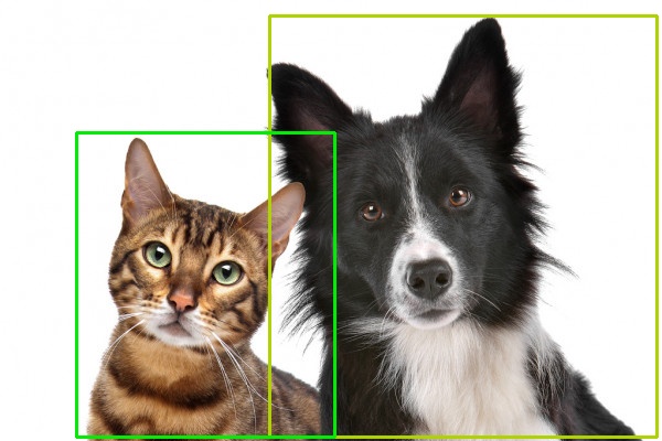
运行结果如下
输出的两类id分别为18和17,查找coco数据集label,这两类代表狗和猫。
环境准备
按照R329提供的docker镜像建立环境,进入docker环境。
`sudo docker pull zepan/zhouyi
`sudo docker run -i -t zepan/zhouyi  /bin/bash
root@0e3c1adc6566:/tf#
在主机端从github上拉下AIPU Model Zoo,并把mobilenet_v2_ssd相关的配置文件拷贝到docker镜像中
同样,把我们准备好的frozen_inference_graph.pb也拷贝过去。
git clone [https://github.com/Zhouyi-AIPU/Model\_zoo.git](https://github.com/Zhouyi-AIPU/Model_zoo.git)
sudo docker cp Model_zoo/mobilenet_v2_ssd/TF 0e3c1adc6566:/root/demos
sudo docker cp frozen_inference_graph.pb 0e3c1adc6566:/root/demos/TF
针对cfg文件,做一下修改。首先试验build模式,由于R329使用的是Z1\_0701的配置,修改target字段,最终cfg文件如下
[Common]
mode = build
use_aqt = True

[Parser]
model_type = tensorflow
model_name = mobilenet_v2_ssd
detection_postprocess = ssd
model_domain = object_detection
input_model = input/frozen_inference_graph.pb
input = image_tensor
input_shape = [1, 300, 300, 3]
output = concat, concat_1
output_dir = ./IR_ft32

[AutoQuantizationTool]
quantize_method = SYMMETRIC
quant_precision = int8
ops_per_channel = DepthwiseConv
reverse_rgb = False
label_id_offset =
dataset_name = COCO
detection_postprocess = ssd
anchor_generator = MULTIPLE_GRID
ts_max_file = input/mobilenet_v2_ssd_max.npy
ts_min_file = input/mobilenet_v2_ssd_min.npy

[GBuilder]
target = Z1_0701
在docker上使用aipubuild命令运行这个cfg文件
root@0e3c1adc6566:~/demos/TF# aipubuild build.cfg
WARNING:tensorflow:
The TensorFlow contrib module will not be included in TensorFlow 2.0.
For more information, please see:
  * [https://github.com/tensorflow/community/blob/master/rfcs/20180907-contrib-sunset.md](https://github.com/tensorflow/community/blob/master/rfcs/20180907-contrib-sunset.md)
  * [https://github.com/tensorflow/addons](https://github.com/tensorflow/addons)
  * [https://github.com/tensorflow/io](https://github.com/tensorflow/io) (for I/O related ops)
If you depend on functionality not listed there, please file an issue.

[I] Parsing model....
[I] [Parser]: Begin to parse tensorflow model mobilenet_v2_ssd...
最终运行成功,获得aipu.bin文件,这个文件需要搭配AIPU runtime在实际的硬件上运行,我手上没有硬件,在此不再赘述。
下面我们使用软件simulator进行软件模拟
预处理
这里是部署阶段的第二个坑。
刚刚我们在build模式下会有以下log
[I] [Parser]: Parser done!
[I] Parse model complete
[I] Quantizing model....
[I] AQT start: model_name:mobilenet_v2_ssd, calibration_method:MEAN, batch_size:1
[I] ==== read ir ================
[I]     float32 ir txt: /tmp/AIPUBuilder_1628145109.123434/mobilenet_v2_ssd.txt
[I]     float32 ir bin2: /tmp/AIPUBuilder_1628145109.123434/mobilenet_v2_ssd.bin
[I] ==== read ir DONE.===========
这里记录了生成的IR路径,我们查看其中的IR /tmp/AIPUBuilder_1628145109.123434/mobilenet_v2_ssd.txt
model_name=mobilenet_v2_ssd
workspace=0
layer_number=104
data_format=NHWC
precision=float32
batch_size=1
model_domain=object_detection
input_tensors=[Preprocessor/sub_0]
output_tensors=[detect_postprocess_nms_boxes,detect_postprocess_nms_box_num_per_class,detect_postprocess_nms_scores,detect_postprocess_nms_keep]

layer_id=0
layer_name=image_tensor
layer_type=Input
layer_bottom=[]
layer_bottom_shape=[]
layer_bottom_type=[]
layer_top=[Preprocessor/sub_0]
layer_top_shape=[[1,300,300,3]]
layer_top_type=[float32]
可以看到第一个Input节点的输出名称是“Preprocessor/sub_0”, 而不是pb文件中image_tensor的输出节点image_tensor:0”
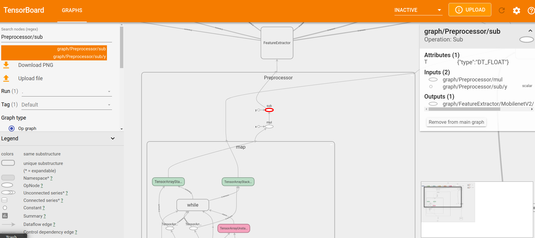
通过tensorboard观察并找到名为Preprocessor/sub的节点。
这个节点是预处理部分的最后一个节点,即aipubuild跳过了整个pb的预处理阶段,直接从后面开始。
相应的,为了保证最后的结果一致,我们需要读取图片后也做pb中的预处理操作,最后的输出作为input输入到AIPU中。
观察pb文件,预处理部分主要的工作是把图像resize到300x300,然后做均一化(img = img / 127.5 - 1)。
因此我们也做相应的操作,生成input.bin文件作为AIPU输入。
import cv2
import numpy as np

img = cv2.imread("test.jpg")
img = cv2.resize(img, (300, 300))
h, w, c = img.shape
image_tensor = img[:,:,:]
image_tensor = image_tensor.reshape([1, h, w, c])
image_tensor = image_tensor - 127.5
image_tensor = np.clip(image_tensor, -128, 127)
image_tensor = image_tensor.astype(np.int8)
image_tensor.tofile("input.bin")
有细心的小伙伴注意到,这里的预处理操作并不是img = img / 127.5 - 1,而仅仅减去了127.5然后就转为np.int8了。
实际上,作为输入我们还要乘以一个反量化参数。但是,在刚刚build阶段,输入的反量化参数并没有打印出来。
原因是由于我们使用的是根据1.13版本pb做出来的max/min文件,并用1.15版本的pb作为模型输入,因此在预处理阶段会有区别。
实际上,哥们儿告诉我,如果使用1.13版本pb,这个反量化参数大约是127.1。
这里我们要相信深度学习网络的健壮性,轻微扰动不影响最终结果,直接减去127.5作为网络输入。
同样,将产生的input.bin 拷贝到docker环境中。
模拟仿真
使用以下cfg文件来跑run模式
[Common]
mode = run
use_aqt = True

[Parser]
model_type = tensorflow
model_name = mobilenet_v2_ssd
detection_postprocess = ssd
model_domain = object_detection
input_model = input/frozen_inference_graph.pb
input = image_tensor
input_shape = [1, 300, 300, 3]
output = concat, concat_1
output_dir = ./IR_ft32

[AutoQuantizationTool]
quantize_method = SYMMETRIC
quant_precision = int8
ops_per_channel = DepthwiseConv
reverse_rgb = False
label_id_offset =
dataset_name = COCO
detection_postprocess = ssd
anchor_generator = MULTIPLE_GRID
ts_max_file = input/mobilenet_v2_ssd_max.npy
ts_min_file = input/mobilenet_v2_ssd_min.npy

[GBuilder]
simulator=aipu_simulator_z1
inputs = input.bin
target = Z1_0701
和之前的build模式相比,在GBuilder 部分添加了我们生成input.bin和simulator的路径。
运行这个cfg文件。
root@0e3c1adc6566:~/demos/TF# aipubuild build.cfg最终,获得了simulator的输出output.bin,output.bin1, output.bin2,output.bin3
标识
这4个output.bin是什么意思?
哥们告诉我,aipubuild会在/tmp/AIPUBuilder_XXX路径下生成一个文件夹,里面有中间运行的一些结果,我们打开其中的量化后的IR观察一下。
model_name=mobilenet_v2_ssd
model_domain=OBJECT_DETECTION
layer_number=105
data_format=NHWC
precision=int8
batch_size=1
input_tensors=[Preprocessor/sub_0]
output_tensors=[detect_postprocess_nms_boxes,detect_postprocess_nms_box_num_per_class,detect_postprocess_nms_scores,detect_postprocess_nms_keep]

layer_id=0
layer_name=image_tensor
layer_type=Input
layer_bottom=[]
layer_bottom_shape=[]
layer_bottom_type=[]
layer_top=[Preprocessor/sub_0]
layer_top_shape=[[1,300,300,3]]
layer_top_type=[int8]

...

layer_id=103
layer_name=SSD_DecodeBox
layer_type=DecodeBox
layer_bottom=[decodebox_activation,concat_0]
layer_bottom_shape=[[1,1917,91],[1,1917,4]]
layer_bottom_type=[uint8,int8]
layer_top=[SSD_DecodeBox_box,SSD_DecodeBox_total_prebox,SSD_DecodeBox_total_class,SSD_DecodeBox_out_score,SSD_DecodeBox_label_perbox]
layer_top_shape=[[1,5000,4],[1,5000],[1,1],[1,5000],[1,5000]]
layer_top_type=[int16,uint16,uint16,uint8,uint16]
weights_type=int16
weights_offset=16901372
weights_size=17384
weights_shape=[8692]
width=16384
height=16384
score_threshold_uint8=127
box_shift=12

layer_id=104
layer_name=detect_postprocess_nms
layer_type=NMS
layer_bottom=[SSD_DecodeBox_box,SSD_DecodeBox_total_prebox,SSD_DecodeBox_total_class,SSD_DecodeBox_out_score]
layer_bottom_shape=[[1,5000,4],[1,5000],[1,1],[1,5000]]
layer_bottom_type=[int16,uint16,uint16,uint8]
layer_top=[detect_postprocess_nms_boxes,detect_postprocess_nms_box_num_per_class,detect_postprocess_nms_scores,detect_postprocess_nms_keep]
layer_top_shape=[[1,1000,4],[1,5000],[1,1000],[1,1000]]
layer_top_type=[int16,uint16,uint8,uint16]
iou_threshold_int16=1228
box_scale_int16=600
box_shift_int16=15
注意到第八行output\_tensors,里面正好有4个输出。
分别表示nms后的box,nms后每一类box的数量,nms后每个box的分数,以及keep。
keep是啥我哥们也不知道。
这4个输出并不是和pb中的输出对应的,而且貌似丢失了标签id信息,标签信息应该在layer id=103的最后一个输出SSD_DecodeBox_label_perbox上,
然而这个tensor并没有作为输出生成bin文件,这就很坑了。
好消息是,我们总算能框出点什么。
坏消息是,我们不知道具体框出的是什么。
Anyway,使用以下代码画出框
import numpy as np
import cv2

boxes = np.fromfile("output.bin", dtype = np.int16)
num_boxes_per_class = np.fromfile("output.bin1", dtype = np.uint16)
score = np.fromfile("output.bin2", dtype = np.uint8)
keep = np.fromfile("output.bin3", dtype = np.uint16)
num_boxes_per_class = np.sum(num_boxes_per_class)

img = cv2.imread("test.jpg")
h, w, c = img.shape
boxes = boxes.reshape([1, 1000, 4])
boxes = boxes[0, :, :].astype(np.float32) / 300
for i in range(num_boxes_per_class):
    box = boxes[i,:]
    y_min = int(box[0] * h)
    x_min = int(box[1] * w)
    y_max = int(box[2] * h)
    x_max = int(box[3] * w)
    start = (x_min, y_min)
    end = (x_max, y_max)
    img = cv2.rectangle(img, start, end, (0, 0, 255), 2)
cv2.imwrite("mark.jpg", img)
需要注意的是,输出需要除以反量化系数,反量化参数在aipubuild运行时有打印
[I]         layer_id:103, layer_top:SSD_DecodeBox_total_class, output_scale:1
[I]         layer_id:103, layer_top:SSD_DecodeBox_label_perbox, output_scale:1
[I]         layer_id:104, layer_top:detect_postprocess_nms_boxes, output_scale:300.0
[I]         layer_id:104, layer_top:detect_postprocess_nms_box_num_per_class, output_scale:1
[I]         layer_id:104, layer_top:detect_postprocess_nms_scores, output_scale:[256.]
[I]         layer_id:104, layer_top:detect_postprocess_nms_keep, output_scale:1
可以看到,标签信息SSD_DecodeBox_label_perbox 输出并打印了反量化系数,但是并没有作为模型的输出生成。
这里应该是SDK的bug了。
box的反量化参数是300,所以我们用box除以300
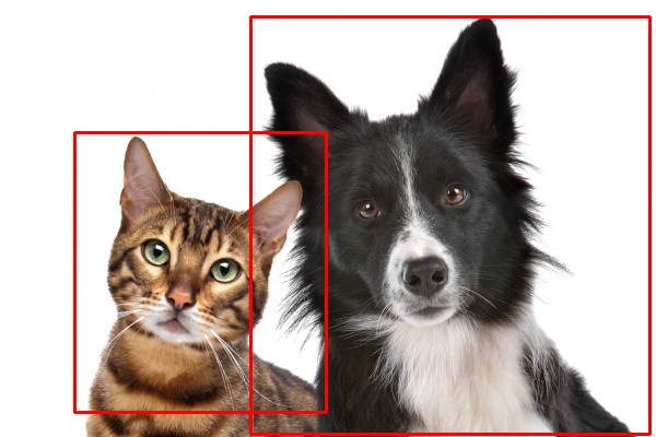
最终的结果如图
至少两个框都找到了,也分出了两类,虽然两类的id是多少没有输出出来。猫的框有点误差,不过也在可接受范围内。
性能分析
在cfg中加入profiler = True可以分析出AIPU在每一个layer使用的时间。
cfg文件如下
[Common]
mode = run
use_aqt = True

[Parser]
model_type = tensorflow
model_name = mobilenet_v2_ssd
detection_postprocess = ssd
model_domain = object_detection
input_model = input/frozen_inference_graph.pb
input = image_tensor
input_shape = [1, 300, 300, 3]
output = concat, concat_1
output_dir = ./IR_ft32

[AutoQuantizationTool]
quantize_method = SYMMETRIC
quant_precision = int8
ops_per_channel = DepthwiseConv
reverse_rgb = False
label_id_offset =
dataset_name = COCO
detection_postprocess = ssd
anchor_generator = MULTIPLE_GRID
ts_max_file = input/mobilenet_v2_ssd_max.npy
ts_min_file = input/mobilenet_v2_ssd_min.npy

[GBuilder]
simulator=aipu_simulator_z1
inputs = input.bin
target = Z1_0701
profile = True
这样,对比非profile时会多生成graph.json和profile_data.bin文件,使用以下命令就可以生成最后的性能报表
root@0e3c1adc6566:~/demos/TF# aipu_profiler graph.json profile_data.bin --frequency 600
Total errors: 0,  warnings: 0
root@0e3c1adc6566:~/demos/TF# ls mobilenet_v2_ssd_perf.html
mobilenet_v2_ssd_perf.html
把mobilenet_v2_ssd_perf.html文件从docker环境中拷贝出来,并用浏览器打开,会发现里面的数据都是0。
这里又是一个坑,哥们告诉我,profile的实现依赖于硬件计数器,但是使用simulator软件模拟并没有实现这个计数器功能。
但是,万能的哥们出马,弄到了真实硬件上的profile.bin数据,生成了最终的报表。
报表中记录了每一层耗费时间,读入多少bytes,写出多少bytes,HWA利用率等指标,
以及整个网络耗时以及访存的数据。
platform target:    Z1_0701
total cycles:    51470162
total time:    85.784ms(@600MHz)
fps:    11.657(@600MHz)
total read bytes:    188230544
total write bytes:    45437152
total read + write bytes:    233667696
average hwa utilization:    57.900%
运行一帧需要85ms左右,这并不包括预处理的时间。
总结
就算有万能的哥们帮忙,依然遇到了好多坑,而最终label的数据还是没办法获取。
在此希望SDK团队能够继续改进,让compass越来越好用。


