Messaging Port
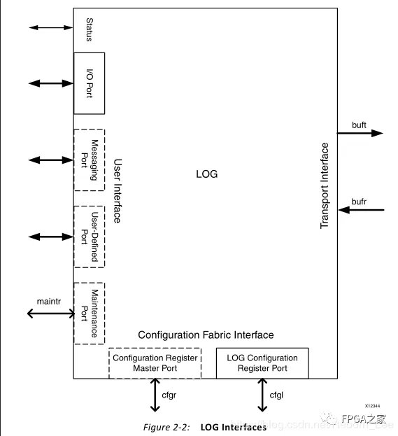
消息传递端口是可选接口(消息也可以组合到I / O端口上,并使用Vivado集成设计环境(IDE)设置视为写入事务)。单独的Messaging端口遵循Initiator / Target样式。
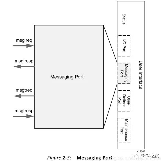
Initiator / Target端口样式允许将针对远程设备的事务与针对本地端点的事务分开。图2-5详细说明了Messaging端口。
本地端点生成的请求放在消息发起方请求(msgireq)端口上,以便在链路上传输。从远程设备收到的响应显示在消息发起者响应(msgiresp)端口上。
来自远程设备的由Serial RapidIO核心接收的请求显示在消息目标请求(msgtreq)端口上。由用户设计生成的对这些请求的响应被放置在消息目标响应(msgtresp)端口上。
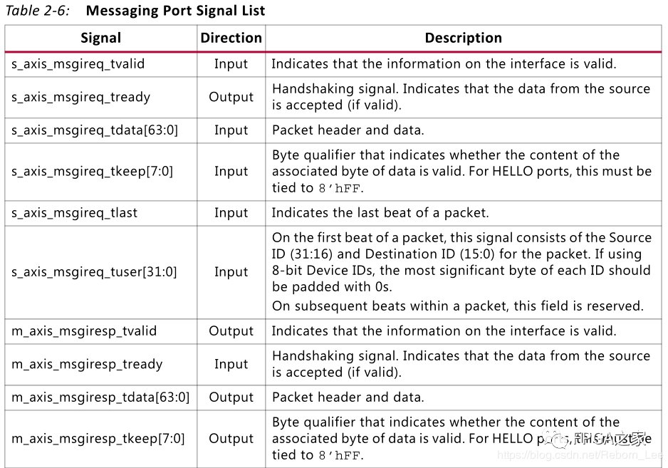
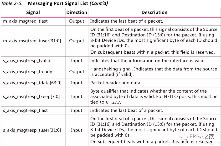
Table 2-6 shows the signals associated with the Messaging port. At the <component_name> level, the following signals are associated with these interfaces:
• s_axis_msgireq* are associated with MSGIREQ.
• m_axis_msgiresp* are associated with MSGIRESP.
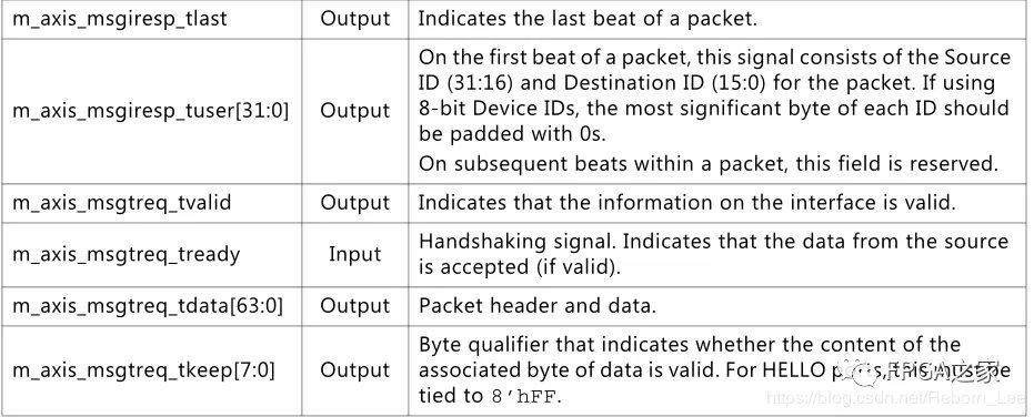
• m_axis_msgtreq* are associated with MSGTREQ.
• s_axis_msgtresp* are associated with MSGTRESP.
其含义都在上表中给出了,但是我还是要挑出一组来用中文解释下:
下面这一组为本地message请求信号:
s_axis_msgireq_tvalid 本地逻辑层Message接口上发起的请求信息是有效的。(输入)
s_axis_msgireq_tready :
握手信号。表明来自于源端的数据被接收了。(输出)
s_axis_msgireq_tdata[63:0] :
包头和数据(输入)
s_axis_msgireq_tkeep[7:0] :
字节限定符,指示相关联的数据字节的内容是否有效。对于HELLO端口,这必须与8'hFF相关联。(输入)
s_axis_msgireq_tlast :
示数据包的最后一拍。(输入)
s_axis_msgireq_tuser[31:0] :
在数据包的第一个节拍上,该信号由数据包的源ID(31:16)和目标ID(15:0)组成。如果使用8位器件ID,每个ID的最高有效字节应填充0。在数据包中的后续节拍中,保留此字段。(输入)
下面这一组是远程设备(另一端)的响应:(含义一致)
m_axis_msgiresp_tvalid Output Indicates that the information on the interface is valid.
m_axis_msgiresp_tready Input Handshaking signal. Indicates that the data from the source is accepted (if valid).
m_axis_msgiresp_tdata[63:0] Output Packet header and data.
m_axis_msgiresp_tkeep[7:0] Output Byte qualifier that indicates whether the content of the associated byte of data is valid. For HELLO ports, this must be tied to 8’hFF.
m_axis_msgiresp_tlast Output Indicates the last beat of a packet.
m_axis_msgiresp_tuser[31:0] Output
On the first beat of a packet, this signal consists of the Source ID (31:16) and Destination ID (15:0) for the packet. If using 8-bit Device IDs, the most significant byte of each ID should be padded with 0s.
On subsequent beats within a packet, this field is reserved.
下面这一组为远端的请求信号:
m_axis_msgtreq_tvalid Output Indicates that the information on the interface is valid.
m_axis_msgtreq_tready Input Handshaking signal. Indicates that the data from the source is accepted (if valid).
m_axis_msgtreq_tdata[63:0] Output Packet header and data.
m_axis_msgtreq_tkeep[7:0] Output Byte qualifier that indicates whether the content of the associated byte of data is valid. For HELLO ports, this must be tied to 8’hFF.
m_axis_msgtreq_tlast Output Indicates the last beat of a packet.
m_axis_msgtreq_tuser[31:0] Output On the first beat of a packet, this signal consists of the Source ID (31:16) and Destination ID (15:0) for the packet. If using 8-bit Device IDs, the most significant byte of each ID should be padded with 0s.
On subsequent beats within a packet, this field is reserved.
下面这一组为本地的响应信号:
s_axis_msgtresp_tvalid Input Indicates that the information on the interface is valid.
s_axis_msgtresp_tready Output Handshaking signal. Indicates that the data from the source is accepted (if valid).
s_axis_msgtresp_tdata[63:0] Input Packet header and data.
s_axis_msgtresp_tkeep[7:0] Input Byte qualifier that indicates whether the content of the associated byte of data is valid. For HELLO ports, this must be tied to 8’hFF.
s_axis_msgtresp_tlast Input Indicates the last beat of a packet.
s_axis_msgtresp_tuser[31:0] Input On the first beat of a packet, this signal consists of the Source ID (31:16) and Destination ID (15:0) for the packet. If using 8-bit Device IDs, the most significant byte of each ID should be padded with 0s.
On subsequent beats within a packet, this field is reserved.
User-Defined Port
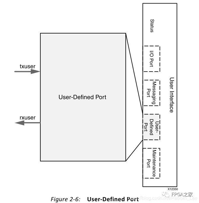
用户定义端口是一个可选端口,有两个AXI4-Stream通道,其中一个通道用于发送方向,一个通道用于接收方向。
用户定义的端口仅使用SRIO Stream格式。用户定义端口如图2-6所示。
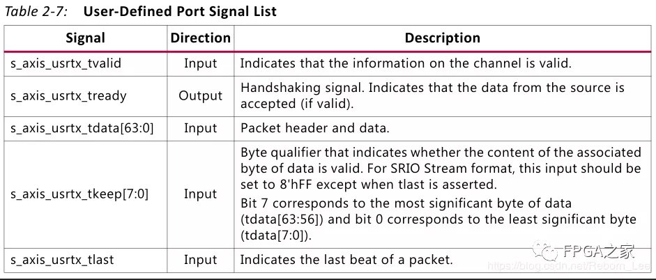
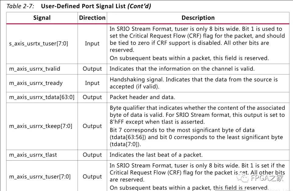
表2-7列出了与用户定义端口关联的信号。s_axis_usrtx *信号与USER_IO_TX接口相关联,m_axis_usrrx 与<component_name>级别的USER\_IO\_RX接口相关联。
Maintenance Port
如果启用了 "维护" 端口, 则它将使用 AXI4-LITE 接口。AXI4-LITE 接口允许用户应用程序定位本地或远程配置空间。
这些端口用到了再说吧。暂时不看了。
END
作者:比特波特
原文链接:https://mp.weixin.qq.com/s/QcfDdckvhAG1VNcRjc\_KGA
微信公众号:
推荐阅读
- 【FPGA】SRIO IP核系统总览以及端口介绍(二)(I/O Port 含义介绍)
- SRIO IP核系统总览以及端口介绍(一)(User Interfaces 之 I/O Port)
- FPGA中的RAM、ROM和CAM;ROM、RAM、DRAM、SRAM、FLASH
更多IC设计技术干货请关注IC设计技术专栏。

