快速连接
👉👉👉【精选】ARMv8/ARMv9架构入门到精通-目录 👈👈👈

1、简介
在学习之前我们先回顾一些概念
术语介绍
- (1)、flat map : 一一映射,也就是虚拟地址=物理地址,官方说法是This means that the input virtual address and output physical address are the same for all translations,此时MMU作用其实就是控制内存属性和权限
(2)、full level 1 table : 一个完整的 L1 页表
Translation regimes
在ARMV8-aarch64的系统中,有如下Translation regimes,而我们今天就以Secure EL3 translation regime为例
Secure EL1&0 translation regime, when EL2 is disabled
Non-secure EL1&0 translation regime, when EL2 is disabled
Secure EL1&0 translation regime, when EL2 is enabled
Non-secure EL1&0 translation regime, when EL2 is enabled
Secure EL2&0 translation regime
Non-secure EL2&0 translation regime
Secure EL2 translation regime
Non-secure EL2 translation regime
Secure EL3 translation regime
2、构建页表示例 -- 一个简单场景Single-level table at EL3
构建页表都需要做哪些事情呢?
- 设置页表基地址VBAR_EL3 (Specify the location of the translation table)
- 初始化MAIR_EL3 (Memory Attribute Indirection Register)
- 配置TCR_EL3 (Configure the translation regime)
- 创建页表 (Generate the translation tables)
- Enable the MMU
(1)、设置页表基地址VBAR_EL3
设置 TTBR0_EL3 = tt_l1_base
// Set the Base address
// ---------------------
LDR x0, =tt_l1_base // Get address of level 1 for TTBR0_EL3
MSR TTBR0_EL3, x0 // Set TTBR0_EL3 (NOTE: There is no TTBR1 at EL3)
思考: 那么 tt_l1_base 到底在哪里呢?
注意,Translation tables必需是对齐的, 如我们示例中,有一个完整的L1页表,4KB的granule,一个完整的L1页表包含512个entries,每个entries是8bytes,所以一个完整的L1页表就是4KB, 所以 tt_l1_base 必需4KB对齐的
tt_l1_base 可以是定义在section段的一个全局变量,初始化全0,注意全0的entry恰好fault entry
section TT,"ax"
.align 12
.global tt_l1_base
tt_l1_base:
.fill 4096 , 1 , 0
那么fault entry又是什么呢?
请参考ARMV8官方文档
In general, a descriptor is one of:
• An invalid or fault entry.
• A table entry, that points to the next-level translation table.
• A block entry, that defines the memory properties for the access.
• A reserved format.
那么 descriptor 又是什么呢??没完没了了是不,descriptor 可以理解成就是 entry.
(2)、初始化MAIR_EL3
我们先看以下MAIR_EL3寄存器的用法,64位的MAIR_EL3寄存器被分成了8个Attr,每一个Attr可以表示一类内存属性
每一个Attr的配置如下:
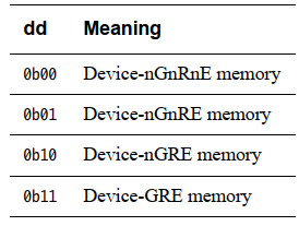
对于Device Memory的配置,dd是啥含义呢?
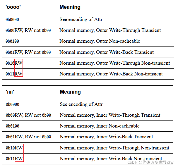
对于Normal Memory的配置,oooo和iiii是啥含义呢?
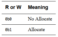
那么RW又是啥含义呢?
好了,寄存器知识复习完了,接下来我们来看实列
如下所示,设置了3个index(3个Attr),分别是:
- index0 (Attr0) : 0x01000100 = Normal, Inner/Outer Non-Cacheable
- index1 (Attr1) : 0x11111111 = Normal, Inner/Outer WB/WA/RA
index2 (Attr2) : 0x00000000 = Device-nGnRnE
// Set up memory attributes
// -------------------------
// This equates to:
// 0 = b01000100 = Normal, Inner/Outer Non-Cacheable
// 1 = b11111111 = Normal, Inner/Outer WB/WA/RA
// 2 = b00000000 = Device-nGnRnE
MOV x0, #0x000000000000FF44
MSR MAIR_EL3, x0
设置完后,留着,后有大用!!
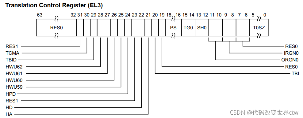
(3)、配置TCR_EL3 (Translation Control Register)
非常复杂的一个系统寄存器,不过还好,哥已经给你整理出了一篇文档,专门介绍TCR,参见《https://blog.csdn.net/weixin_42135087/article/details/112462416》, 本文就不再详细介绍这些比特位了。
然后我们就可以看示例代码了,牛批不是吹,你看这一个小小寄存器干了了多少事情:
- 配置了虚拟地址有效位是 39 ,也就意味着
translation starts at L1, Why ??? - 页表所在内存的内存属性,Inner WB/WA、Outer WB/WA、Inner Shareable
- ignore top bytes
- 4KB granule
输出32位物理地址
// Set up TCR_EL3
// ---------------
MOV x0, #0x19 // T0SZ=0b011001 Limits VA space to 39 bits,
// translation starts @ l1
ORR x0, x0, #(0x1 << 8) // IGRN0=0b01 Walks to TTBR0 are Inner WB/WA
ORR x0, x0, #(0x1 << 10) // OGRN0=0b01 Walks to TTBR0 are Outer WB/WA
ORR x0, x0, #(0x3 << 12) // SH0=0b11 Inner Shareable
// TBI0=0b0 Setting this bit causes the top 8 bits of the virtual address to be ignored
// TG0=0b00 4KB granule
// IPS=0 32-bit PA space
MSR TCR_EL3, x0
我们再来看看,为什么 配置了虚拟地址有效位是 39 ,就是意味着
translation starts at L1?
请参考ARMV8的官方文档,这是address translation的格式要求,虚拟地址有效位是39,也就是BIT[38:0], 所以也就不存在Level 0 table了,TTBR_EL3直接执行Level 1 Table。
然后我们再来看每一个Table或每一个entry能够cover住的范围:- L0 table: 512GB per entry -- 注意,本示例中,没有L 0 Table
- L1 tables: Each table covers 512GB, 1GB per entry
- L2 tables: Each table covers 1GB, 2MB per entry
- L3 tables: Each table covers 2MB, 4KB per entry
再配置好MMU相关的寄存器后,一定要记得 Invalidate TLBs, 这里操作的是Secure EL3 translation regime, 所以只要invalid EL3的TLB即可:
// Invalidate TLBs
// ----------------
TLBI ALLE3
DSB SY
ISB
(4)、创建页表
我们创建一个啥样子的页表好呢?
TTBR0_EL3 指向 Level 1 Table, L1 Table中只有3个entry,每个entry管理者1G内存,也就是一共管理了3G内存的页表,一一映射。如下图所示:就是一张这样的表
示例代码如下:(吊不吊?,反正不是我写的)
LDR x1, =tt_l1_base // Address of L1 table
// [0]: 0x0000,0000 - 0x3FFF,FFFF
LDR x0, =TT_S1_DEVICE_nGnRnE // Entry template
// AP=0, RW
// Don't need to OR in address, as it is 0
STR x0, [x1]
// [1]: 0x4000,0000 - 0x7FFF,FFFF
LDR x0, =TT_S1_DEVICE_nGnRnE // Entry template
// AP=0, RW
ORR x0, x0, #0x40000000 // 'OR' template with base physical address
STR x0, [x1, #8]
// [2]: 0x8000,0000 - 0xBFFF,FFFF (DRAM on the VE and Base Platform)
LDR x0, =TT_S1_NORMAL_WBWA // Entry template
ORR x0, x0, #TT_S1_INNER_SHARED // ‘OR’ with inner-shareable attribute
// AP=0, RW
ORR x0, x0, #0x80000000 // 'OR' template with base physical address
STR x0, [x1, #16]
DSB SY
注意:一般操作系统或软件的实现本例这样的场景时,会在运行时给L1 Table的其它entry赋0,而不像本例在编译的时候,就定义了初始化位0的数组。
那么上述示例中的TT_S1_DEVICE_nGnRnE 、TT_S1_NORMAL_WBWA 、TT_S1_DEVICE_nGnRnE 又是什么鬼? 其实就是定义了3个内存属性模板,每个模板都是Upper Attributes + Lower Attributes的集合
内存属性相关比特位的解释如下:
- Indx = b01, take Type information from entry [1] in the MAIR
- NS = b0, output physical addresses are Secure
- AP = b00, address is readable and writeable
- SH = b00, Non-shareable
- AF = b1, Access Flag is pre-set. No Access Flag Fault is generated on access
- nG = Not used at EL3
- Contig = b0, the entry is not part of a contiguous block
- PXN = b0, block is executable. This attribute is called XN at EL3.
- UXN = Not used at EL3
(5)、Enable the MMU
经历前面的4个步骤,是不是觉得已经大功告成了? 没错,基本完事了,还差最后一步,打开MMU。
// Enable MMU
// -----------
MOV x0, #(1 << 0) // M=1 Enable the stage 1 MMU
ORR x0, x0, #(1 << 2) // C=1 Enable data and unified caches
ORR x0, x0, #(1 << 12) // I=1 Enable instruction fetches to allocate
// into unified caches
// A=0 Strict alignment checking disabled
// SA=0 Stack alignment checking disabled
// WXN=0 Write permission does not imply XN
// EE=0 EL3 data accesses are little endian
MSR SCTLR_EL3, x0
ISB
MMU就这样被打开,至此一个构建开启MMU构建页表的完整示例就介绍完了,是不是觉得非常遗憾? 感觉学到了什么,又好像没学到什么。没事慢慢来,后面还有。
3、构建页表示例 -- 稍微复杂一点场景Multiple levels of table at EL3
由于很多步骤在上一节都已经讲述过了,所以本节讲述的仅仅是创建页表 (Generate the translation tables)
- 设置页表基地址VBAR_EL3 (Specify the location of the translation table)
- 初始化MAIR_EL3 (Memory Attribute Indirection Register)
- 配置TCR_EL3 (Configure the translation regime)
- 创建页表 (Generate the translation tables)
- Enable the MMU
先构建L1 table,在L1 table中只让 3个entries有效。其中:
- entry0 : 指向block,即
0x0000,0000 - 0x3FFF,FFFF - entry1 : 指向block,即
0x4000,0000 - 0x7FFF,FFFF - entry2 : 指向L2 table,控制着
0x8000,0000 - 0xBFFF,FFFF地址空间
其实我们就是想建立一张下图所示的表,entry0 和entry1还是依然指向block内存,entry2则指向了二级页表
如下示例代码,便是L1 Table的实现
//
// Generate L1 table
//
LDR x1, =tt_l1_base // Address of L1 table
// [0]: 0x0000,0000 - 0x3FFF,FFFF
LDR x0, =TT_S1_DEVICE_nGnRnE // Entry template
// AP=0, RW
// Don't need to OR in address, as it is 0
STR x0, [x1]
// [1]: 0x4000,0000 - 0x7FFF,FFFF
LDR x0, =TT_S1_DEVICE_nGnRnE // Entry template
// AP=0, RW
ORR x0, x0, #0x40000000 // 'OR' template with base physical address
STR x0, [x1, #8]
// [2]: 0x8000,0000 - 0xBFFF,FFFF (DRAM on the VE and Base Platform)
LDR x2, =tt_l2_base // Get address of L2 table
LDR x0, =TT_S1_TABLE // Entry template for pointer to next level table
ORR x0, x0, x2 // Combine template with L2 table Base address
STR x0, [x1, #16] // Write template into entry table[2]
如下示例代码,便是L2 Table的实现
//
// Generate L2 table
//
…
LDR x0, =tt_l2_base // Address of first L2 table
// The L2 table covers the address range:
// 0x8000_0000 - 0xBFFF_FFFF
//
// This example only populates entry 0, which covers:
// 0x8000_0000 - 0x801F_FFFF
LDR x1, =tt_l2_base // Address of L1 table
LDR x0, =TT_S1_NORMAL_WBWA // Entry template
ORR x0, x0, #TT_S1_INNER_SHARED // 'OR' with inner-shareable attribute
// AP=0, RW
ORR x0, x0, #0x80000000 // 'OR' template with base physical address
STR x0, [x1]
DSB SY
如下示例代码,便是L1 Table的实现
4、构建页表示例 -- 继续复杂一点场景Single-level table at EL1
在上面两个小节已经讲述了Single-level table 、Multi-level table 的配置和映射场景,当然都是发生在EL3的。 本节再来继续看一下如果是EL1呢?
配置和建立页表需要做哪些事情,由于在前面都已经讲述过了,本节就不在重复描述了,我们来看看EL1和EL3不一样的地方。
- 设置页表基地址VBAR_EL3 (Specify the location of the translation table)
- 初始化MAIR_EL3 (Memory Attribute Indirection Register)
- 配置TCR_EL3 (Configure the translation regime)
- 创建页表 (Generate the translation tables)
- Enable the MMU
For NS.EL1:
- Configure SCR_EL3
- Configure HCR_EL2
(1)、Configure SCR_EL3
// Configure SCR_EL3
// ------------------
MOV x0, #1 // NS=1
ORR x0, x0, #(1 << 1) // IRQ=1 IRQs routed to EL3
ORR x0, x0, #(1 << 2) // FIQ=1 FIQs routed to EL3
ORR x0, x0, #(1 << 3) // EA=1 SError routed to EL3
ORR x0, x0, #(1 << 8) // HCE=1 HVC instructions are enabled
ORR x0, x0, #(1 << 10) // RW=1 Next EL down uses AArch64
ORR x0, x0, #(1 << 11) // ST=1 Secure EL1 can access timers
MSR SCR_EL3, x0
(2)、Configure HCR_EL2
// Configure HCR_EL2
// ------------------
ORR w0, wzr, #(1 << 3) // FMO=1
ORR x0, x0, #(1 << 4) // IMO=1
ORR x0, x0, #(1 << 31) // RW=1 NS.EL1 is AArch64
// TGE=0 Entry to NS.EL1 is possible
// VM=0 Stage 2 MMU disabled
MSR HCR_EL2, x0
关注"Arm精选"公众号,备注进ARM交流讨论区。


