
来自微信公众号 “数字芯片实验室”
STEP 1: 编写Verilog设计和仿真文件
• 建立一个新的文件夹,存放所有的项目文件
• 编写设计文件Counter.v
/*****************************************************************************************************
* Description:                 Counter for VCS Lab
                          - When rst==1, thenthe counter returns to 0
                          - The counter countsfrom 0 to 19 at every rising edge of clk
                          - After it reaches19, the next rising edge the counter resets to 0
*****************************************************************************************************/
`timescale 1ns / 1ps

module Counter(
   rst,
   clk,
    c
   );

   input rst;
   input  clk;
   output reg [4:0] c;

   always @ (posedge clk)
   begin
       if (rst)
       begin
           c <= 5'h00;
       end
       else
       begin
           if (c < 5'h13)
           begin
                c <= c + 1;
           end
           else
           begin
                c <= 5'h00;
           end
       end
   end

endmodule
• 编写TestBench文件Counter\_tb.v
/*****************************************************************************************************
* Description:                 Test bench of Counter for VCSLab
********************************/
`timescale 1ns / 1ps

module Counter_tb;

   reg  rst;
   reg  clk;

   wire [4:0] c;

   Counter DUT(
   .rst(rst),
   .clk(clk),
   .c(c)
    );

   initial
   begin

       $dumpfile("Counter.vcd");
       $dumpvars(0, Counter_tb);

        rst = 1;
       clk = 0;

       #40
       rst = 0;

       #600
       rst = 1;

       #40
       rst = 0;

       #600

       #20
       $finish;

    end
   always
       #10 clk = !clk;
endmodule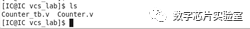
STEP 2: Compiling and simulating your code
• 在相应的项目文件目录(vcs\_lab)下编译design和testbench文件
vcs Counter.v Counter_tb.v在这个阶段如果报出编译Error,可以根据相关信息进行Debug
工具打印出
../simv up to date表示编译成功,并且该目录下会生成一个可执行文件simv
输入./simv ,工具会打印出“VCS Simulation Report”,同时生成Testbench所指定的波形文件Counter.vcd
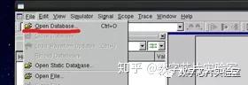
STEP 3: 使用dve显示波形界面
输入
dve &点击“File/Open Database”
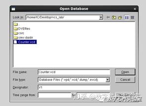
选择“Counter.vcd” 文件
然后在Hierachy下出现设计的层次关系,在log里显示文件打开成功。
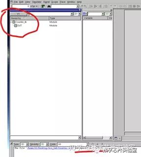
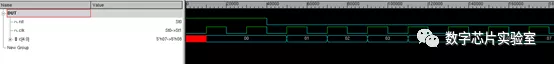
然后点击DUT (这是Testbench中设计的例化名), 选择 “Add to Waves”.
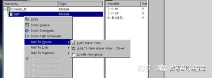
这样就可以看到设计的仿真波形了
上面示例就是最简单的VCS 仿真过程。在实际工作中,还会用到VCS的debug功能。此时需要加上编译选项-debug\_access+all
另外还要加上-lca选项,不然工具会一直报告
Error-[LCA_FEATURES_NEED_OPTION] Invalidusage
 Limited Customer Availability feature is used.
  The'Debug Access' flow requires a special option.
  Youcan enable it by adding '-lca' to the command line.
其他和上述流程一样。
vcs -lca -debug_access+all Counter.vCounter_tb.v
./simv -gui &
本文转载自公众号:芯片数字实验室
原文链接:https://mp.weixin.qq.com/s/LIISmg\_Vl6-A2pDh65c4iA
未经作者同意,请勿转载!
推荐阅读
想了解更多内容,欢迎关注芯片数字实验室专栏

