ADC
模拟数字转换器即A/D转换器,或简称ADC,通常是指一个将模拟信号转变为数字信号的电子元件。通常的模数转换器是将一个输入电压信号转换为一个输出的数字信号。
MicroPython
import machine
import utime

sensor_temp = machine.ADC(4)
conversion_factor = 3.3 / (65535)

while True:
    reading = sensor_temp.read_u16() * conversion_factor

    # The temperature sensor measures the Vbe voltage of a biased bipolar diode, connected to the fifth ADC channel
    # Typically, Vbe = 0.706V at 27 degrees C, with a slope of -1.721mV (0.001721) per degree.
    temperature = 27 - (reading - 0.706)/0.001721
    print(temperature)
    utime.sleep(2)
C/C++
#include <stdio.h>
#include "pico/stdlib.h"
#include "hardware/adc.h"  // For ADC input:
#include "hardware/dma.h"

#include "pico/multicore.h"// For resistor DAC output:
#include "hardware/pio.h"
#include "resistor_dac.pio.h"

// Channel 0 is GPIO26
#define CAPTURE_CHANNEL 0
#define CAPTURE_DEPTH 1000

uint8_t capture_buf[CAPTURE_DEPTH];

void core1_main();

int main() {
    stdio_init_all();

    // Send core 1 off to start driving the "DAC" whilst we configure the ADC.
    multicore_launch_core1(core1_main);

    // Init GPIO for analogue use: hi-Z, no pulls, disable digital input buffer.
    adc_gpio_init(26 + CAPTURE_CHANNEL);

    adc_init();
    adc_select_input(CAPTURE_CHANNEL);
    adc_fifo_setup(
        true,    // Write each completed conversion to the sample FIFO
        true,    // Enable DMA data request (DREQ)
        1,       // DREQ (and IRQ) asserted when at least 1 sample present
        false,   // We won't see the ERR bit because of 8 bit reads; disable.
        true     // Shift each sample to 8 bits when pushing to FIFO
    );

    adc_set_clkdiv(0);

    printf("Arming DMA\n");
    sleep_ms(1000);
    // Set up the DMA to start transferring data as soon as it appears in FIFO
    uint dma_chan = dma_claim_unused_channel(true);
    dma_channel_config cfg = dma_channel_get_default_config(dma_chan);

    // Reading from constant address, writing to incrementing byte addresses
    channel_config_set_transfer_data_size(&cfg, DMA_SIZE_8);
    channel_config_set_read_increment(&cfg, false);
    channel_config_set_write_increment(&cfg, true);

    // Pace transfers based on availability of ADC samples
    channel_config_set_dreq(&cfg, DREQ_ADC);

    dma_channel_configure(dma_chan, &cfg,
        capture_buf,    // dst
        &adc_hw->fifo,  // src
        CAPTURE_DEPTH,  // transfer count
        true            // start immediately
    );

    printf("Starting capture\n");
    adc_run(true);

    // Once DMA finishes, stop any new conversions from starting, and clean up
    // the FIFO in case the ADC was still mid-conversion.
    dma_channel_wait_for_finish_blocking(dma_chan);
    printf("Capture finished\n");
    adc_run(false);
    adc_fifo_drain();

    // Print samples to stdout so you can display them in pyplot, excel, matlab
    for (int i = 0; i < CAPTURE_DEPTH; ++i) {
        printf("%-3d, ", capture_buf[i]);
        if (i % 10 == 9)
            printf("\n");
    }
}

#define OUTPUT_FREQ_KHZ 5
#define SAMPLE_WIDTH 5
// This is the green channel on the VGA board
#define DAC_PIN_BASE 6

void core1_main() {
    PIO pio = pio0;
    uint sm = pio_claim_unused_sm(pio0, true);
    uint offset = pio_add_program(pio0, &resistor_dac_5bit_program);
    resistor_dac_5bit_program_init(pio0, sm, offset,
        OUTPUT_FREQ_KHZ * 1000 * 2 * (1 << SAMPLE_WIDTH), DAC_PIN_BASE);
    while (true) {
        // Triangle wave
        for (int i = 0; i < (1 << SAMPLE_WIDTH); ++i)
            pio_sm_put_blocking(pio, sm, i);
        for (int i = 0; i < (1 << SAMPLE_WIDTH); ++i)
            pio_sm_put_blocking(pio, sm, (1 << SAMPLE_WIDTH) - 1 - i);
    }
}
CMakeList.txt:
add_executable(adc_dma_capture
        dma_capture.c
        )

pico_generate_pio_header(adc_dma_capture ${CMAKE_CURRENT_LIST_DIR}/resistor_dac.pio)

target_link_libraries(adc_dma_capture
        pico_stdlib
        hardware_adc
        hardware_dma
        # For the dummy output:
        hardware_pio
        pico_multicore
        )

# create map/bin/hex file etc.
pico_add_extra_outputs(adc_dma_capture)

# add url via pico_set_program_url
example_auto_set_url(adc_dma_capture)
PWM
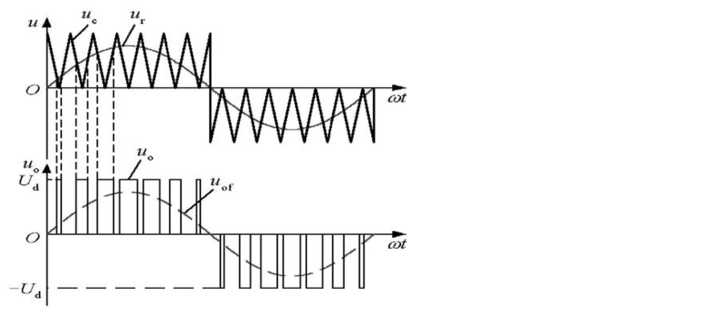
脉冲宽度调制是一种模拟控制方式,根据相应载荷的变化来调制晶体管基极或MOS管栅极的偏置,来实现晶体管或MOS管导通时间的改变,从而实现开关稳压电源输出的改变。这种方式能使电源的输出电压在工作条件变化时保持恒定,是利用微处理器的数字信号对模拟电路进行控制的一种非常有效的技术。
MicroPython
import time
from machine import Pin, PWM


# Construct PWM object, with LED on Pin(25).
pwm = PWM(Pin(25))

# Set the PWM frequency.
pwm.freq(1000)

# Fade the LED in and out a few times.
duty = 0
direction = 1
for _ in range(8 * 256):
    duty += direction
    if duty > 255:
        duty = 255
        direction = -1
    elif duty < 0:
        duty = 0
        direction = 1
    pwm.duty_u16(duty * duty)
    time.sleep(0.001)
C/C++
以呼吸灯为例,LED为核心板上的。
#include "pico/stdlib.h"
#include <stdio.h>
#include "pico/time.h"
#include "hardware/irq.h"
#include "hardware/pwm.h"

void on_pwm_wrap() {
    static int fade = 0;
    static bool going_up = true;
    // Clear the interrupt flag that brought us here
    pwm_clear_irq(pwm_gpio_to_slice_num(PICO_DEFAULT_LED_PIN));

    if (going_up) {
        ++fade;
        if (fade > 255) {
            fade = 255;
            going_up = false;
        }
    } else {
        --fade;
        if (fade < 0) {
            fade = 0;
            going_up = true;
        }
    }
    // Square the fade value to make the LED's brightness appear more linear
    // Note this range matches with the wrap value
    pwm_set_gpio_level(PICO_DEFAULT_LED_PIN, fade * fade);
}

int main() {
    // Tell the LED pin that the PWM is in charge of its value.
    gpio_set_function(PICO_DEFAULT_LED_PIN, GPIO_FUNC_PWM);
    // Figure out which slice we just connected to the LED pin
    uint slice_num = pwm_gpio_to_slice_num(PICO_DEFAULT_LED_PIN);

    pwm_clear_irq(slice_num);
    pwm_set_irq_enabled(slice_num, true);
    irq_set_exclusive_handler(PWM_IRQ_WRAP, on_pwm_wrap);
    irq_set_enabled(PWM_IRQ_WRAP, true);

    // counter is allowed to wrap over its maximum range (0 to 2**16-1)
    pwm_config config = pwm_get_default_config();
    // Set divider, reduces counter clock to sysclock/this value
    pwm_config_set_clkdiv(&config, 4.f);
    // Load the configuration into our PWM slice, and set it running.
    pwm_init(slice_num, &config, true);

    while (1)
        tight_loop_contents();
}
CMakeList.txt:
add_executable(pwm_led_fade
        pwm_led_fade.c
        )

# Pull in our pico_stdlib which pulls in commonly used features
target_link_libraries(pwm_led_fade pico_stdlib hardware_pwm)

# create map/bin/hex file etc.
pico_add_extra_outputs(pwm_led_fade)

# add url via pico_set_program_url
example_auto_set_url(pwm_led_fade)本文转自:Github
作者:zihan987
推荐阅读
- Raspberry Pi Pico教程进阶篇:I2C&SPI
- 阿chai带你学Raspberry Pi Pico基础篇:IO口的使用/UART通信/中断/定时器
- 阿chai带你学Raspberry Pi Pico:环境搭建与简介
更多嵌入式AI技术相关内容请关注嵌入式AI专栏。


