Arm应用处理器从Arm926(应用于手机和嵌入式系统)开始,历经
- Arm11,
- 单核Cortex-A8,
- 第一个真正的多核系统Cortex-A9和后面的Cortex-A5,
- 第一个大小核系统A15+A7到后面的A17+A7,A57/A72/A73+A53
- 新的大小核DynamIQ系统A75, A76, A77, A78 + A55
- 最新的Armv9 CPU A710/A720+A510系统
Arm应用处理器始终以极佳的能效,低功耗应用于包括手机在内的移动设备,因而它们的低功耗设计,电源管理是重要的设计考虑。
本文讨论arm应用处理的电源管理的硬件的变迁过程。总的来说arm应用处理器的电源管理硬件设计是随着SoC系统从单核-》多核-》大小核-》DynamIQ的复杂度而复杂的,但是为了提供统一的电源管理接口和简化和统一软件上下电的复杂度,arm在这个进化过程,
- 改进了硬件设计,提供了power policy unit(PPU)这样的标准电源管理组件,通过标准的P-channel硬件接口来统一电源管理。
- 通过硬件对上下电的支持来简化和标准化软件电源管理,比如支持硬件自动的刷cache,硬件自动的退出coherency,硬件的CPU静默(Quiescence)和GIC静默请求和应答等。
- 定义了系列的软件接口,如PSCI,SCMI,通过明确的软件分层和接口定义,提供更加通用portable的软件系统。
Cortex-A9多核系统
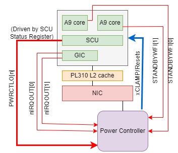
从Cortex-A9说起,A9MP多核系统需要更好的电源控制,如动态控制一个CPU core power down和power up。A9MP提供了一些特用的硬件信号与电源控制器连接和通信,运行在A9应用处理器上的软件通知电源控制器需要对那个CPU进行哪种控制(Power Down或是Power UP或进入/退出Dormant mode)。A9MP提供了PWRCTLO这组信号,可以连接到电源控制器。电源管理软件可以设置A9MP SCU CPU Power Status Register寄存器设置CPU要进入的power状态(power-off或是dormant模式),当A9MP通过执行WFI指令进入WFI低功耗模式,A9MP硬件会驱动PWRCTLO这组信号来表示要进入的power状态,从而告知power controller。
A9的power Down过程大致为:
- 软件保存CPU core的通用寄存器,系统寄存器值到内存中。
- 软件执行DSB指令
- 软件清除SCTLR.C bit,这防止数据进一步分配在cache中
- 软件clean and invalidate L1数据cache中的数据到下级内存,如DRAM
- 软件执行DSB指令
- 软件执行CLREX指令
- 软件清除ACTLR.SMP bit, 这使这个CPU核退出硬件coherency(SCU不再snoop这个核),并且SCU不再把TLB invaldate和cache maintainance操作到这个核
- 软件将原来发送给这个核的中断disable(保留wakeup中断)或迁移到其他核,disable这个CPU对应的GIC CPU interface
- 软件执行ISB,保证之前系统操作完成
- 软件将要进入的power状态设置到SCU CPU power status register
- 软件执行DSB指令,保证之前的内存和cache maintainance操作完成,包括outstanding的AXI, ACP传输。
- 软件执行WFI指令。当这个核进入静默状态,A9MP硬件会驱动STANDBYWFI信号,通过它告知与其连接的电源控制器,CPU已进入idle状态。SCU硬件也会驱动PWRCTLO信号告知电源控制器这个核要进入的power状态
- 电源控制器驱动CLAMP信号使能核的钳位电路
- 电源控制器切断这个核的电源
A9时代的SoC的电源控制比较简单,一般是芯片设计公司自己设计的PMIC,采用状态机方式来实现控制。
A9时代电源管理比较容易犯错误的地方有:
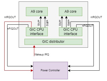
- 在执行DSB+WFI之前,没有做好第8步。也就是在执行WFI—电源控制器将电源切断这中间,还有中断通过GIC的CPU interface和CPU连接的nIRQ/nFIQ将中断发送给CPU。这可能导致的问题是:
CPU已经执行了WFI,通知了power controller切断电源,这两个操作有时间差,如果这个时间差过程中,有一个中断通过nIRQ/nFIQ发送给CPU,这会唤醒进入WFI低功耗状态的CPU(即使CPSR.I/F bit禁止了IRQ/FIQ也会唤醒),CPU会继续执行IRQ handler或是执行WFI之下的指令(取决于CPSR.I/F bit设置),这可能保护内存访问指令,但在这些内存访问(如还在outstanding的AXI访问)硬件操作没有完成之前,就被power controller切断电源。这会使interconnect系统中存在没法完成的AXI传输,最终导致硬件系统的挂死。在我支持客户的经验中,这种问题通常在系统的上下电压力测试时被发现。 - 硬件系统集成时,将GIC CPU interface的nIRQOUT/nFIQOUT而不是nIRQ/nFIQ连接到CPU的nIRQ/nFIQ. 首先这是设计错误,然后可能更容易导致上面1的问题。
GIC CPU interface的nIRQOUT/nFIQOUT设计目的为让唤醒(wakeup)中断可以在CPU interface disable的情况下(这时包括wakeup的中断不会通过nIRQ/nFIQ发送给CPU),GIC CPU interface还可以产生nIRQOUT/nFIROUT信号,通知power controller给对应的CPU核上电。
A7+A1x big.LITTLE系统
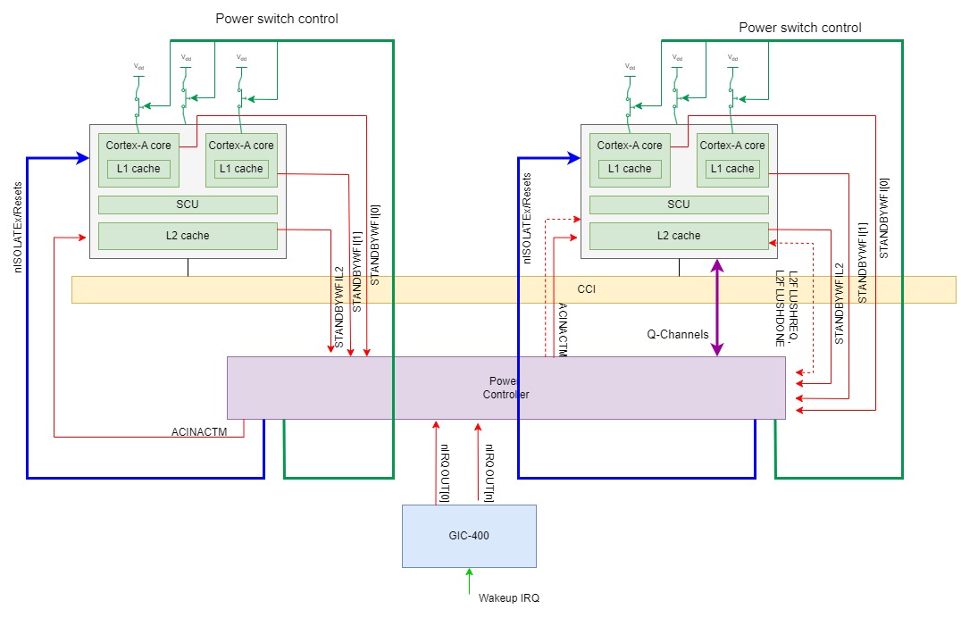
之后出现了big.LITTLE包括A7+A15/A17系统,支持通过ACE接口和CCI一致性互联实现ccluster之间的硬件cache一致性。在cluster层面上比A9MP的系统多了L2 cache,电源管理的时候可以关掉一个cluster里面的一些CPU核或者整个cluster. A17还能支持通过power controller硬件L2FLUSHREQ信号请求L2 cache自己在cluster下电时做clean and invalidate操作。为了让power controller请求/了解cluster的L2 memory system的idle状态,引入了STANDBYWFIL2信号,它可以连接到power controller以显示L2的硬件idle状态。引入了ACINACTM信号,power controller设置这个信号为高时,向cluster保证不再会有任何从一致性互联(CCI)发送给这个cluster。支持ACP port的A15, A17还引入了AINACTS信号,当power controller将这个信号置高时,向cluster保证不再会有任何从ACP的传输发送给这个cluster。
以Cortex-A15 core为例,单个CPU 核power down的过程如下:
1. Clear the SCTLR.C bit, or HSCTLR.C bit if in Hyp mode, to prevent additional data
cache allocation.
2. Clean and invalidate all data from the L1 data cache. The L2 duplicate snoop tag RAM
for this processor is now empty. This prevents any new data cache snoops or data cache
maintenance operations from other processors in the multiprocessor being issued to this
processor.
3. Switch the processor from Symmetric Multiprocessing (SMP) mode to Asymmetric
Multiprocessing (AMP) mode by clearing the ACTLR SMP bit. Clearing the SMP bit
enables the processor to be taken out of coherency by preventing the processor from
receiving cache, TLB, or BTB maintenance operations broadcast by other processors in
the multiprocessor.
4. Ensure that the system does not send interrupts to the processor that is being powered
Down. 软件将原来发送给这个核的中断disable(保留wakeup中断)或迁移到其他核,disable这个CPU对应的GIC CPU interface.
5. Execute an ISB instruction to ensure that all of the CP15 register changes from the
previous steps have been committed.
6. Execute a DSB instruction to ensure that all cache, TLB and branch predictor maintenance
operations issued by any processor in the multiprocessor before the SMP bit was cleared
have completed.
7. Execute a WFI instruction and wait until the STANDBYWFI output is asserted to indicate
that the processor is in idle and low power state.
8. Activate the processor and the NEON and VFP output clamps by asserting the
nISOLATECPU and nISOLATECX inputs LOW.
9. Remove power from the processor and the NEON and VFP power domains.
Power off一个A15 cluster时,需要在下面条件都满足下,STANDBYWFIL2才会被拉高(assert):
这个cluster中所有core都已经进入WFI低功耗状态,即除最后一个核(也就是正在执行power down的最后这个核)之外,其他核都被power down了。Cluster中的所有核的STANDBYWFI都已经assert了。
SoC将ACINACTM信号拉起,表示外部内存系统不再发snoop给这个cluster
当L2 memory sytem完成ACE,AXI端口上所有的outstanding传输时,这个cluster可以进入L2 WFI低功耗状态,这时cluster可以拉高STANDBYWFIL2输出,通知power controller L2进入了idle状态了。
Cortex-A15 Cluster power down的过程如下:
1. Ensure all non-lead processors are in shutdown mode
2. For the remaining and lead processor, Clear the SCTLR.C bit, or HSCTLR.C bit if in Hyp mode, to prevent additional datacache allocation.
Clean and invalidate all data from the L1 data cache. The L2 duplicate snoop tag RAM
for this processor is now empty. This prevents any new data cache snoops or data cache
maintenance operations from other processors in the multiprocessor being issued to this
processor.
3. Ensure the ACP master does not send further requests to the individual processor. Assert
AINACTS to idle the ACP slave interface after all responses are received.
4. Ensure any system snooping to the Cortex-A15 MPCore processor is disabled.
5. Disable L2 prefetches by writing 0x00000400 to the L2 Prefetch Control Register.
6. Execute an ISB instruction to ensure the L2 Prefetch Control Register write is complete.
7. Execute a DSB instruction to ensure completion of any prior prefetch requests.
8. Clean and invalidate all data from the L2 data cache.
9. Assert ACINACTM to idle the AXI master interface after all responses are received.
10. Ensure system interrupts to the Cortex-A15 MPCore processor are disabled.
11. Set the DBGOSDLR.DLK, OS Double Lock control bit, that forces the debug interfaces
to be quiescent.
12. Do following steps
1. Switch the processor from Symmetric Multiprocessing (SMP) mode to Asymmetric
Multiprocessing (AMP) mode by clearing the ACTLR SMP bit. Clearing the SMP bit
enables the processor to be taken out of coherency by preventing the processor from
receiving cache, TLB, or BTB maintenance operations broadcast by other processors in
the multiprocessor.
2. Ensure that the system does not send interrupts to the processor that is being powered
down.
3. Execute an ISB instruction to ensure that all of the CP15 register changes from the
previous steps have been committed.
4. Execute a DSB instruction to ensure that all cache, TLB and branch predictor maintenance
operations issued by any processor in the multiprocessor before the SMP bit was cleared
have completed.
5. Execute a WFI instruction and wait until the STANDBYWFI output is asserted to indicate
that the processor is in idle and low power state.
6. Activate the processor and the NEON and VFP output clamps by asserting the
nISOLATECPU and nISOLATECX inputs LOW.
7. Remove power from the processor and the NEON and VFP power domains.

13. Wait until the STANDBYWFIL2 output is asserted to indicate that the L2 memory
system is idle.
14. Activate the output clamps of the Cortex-A15 MPCore processor in the SoC.
15. Remove power from the L2 control and L2 RAM power domains.
A15,A17支持CPU核和cluster级别的dynamic retention模式。当进入WFI低功耗状态,它的时钟停止了,这时可以让power controller将供电电压降低,但是CPU,Cluster的状态(如寄存器值,RAM中的内容)不丢失。这个状态叫Retention. Retention要求power controller可以保证在退出retention过程中,在重新enable时钟之前先将电压恢复到正常可运行的电压值。
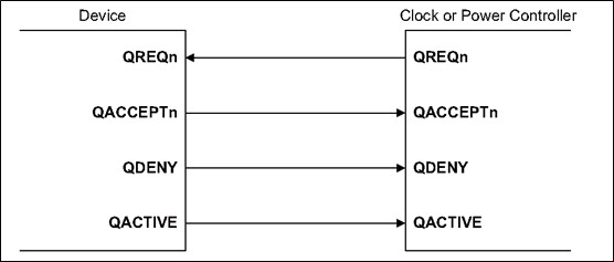
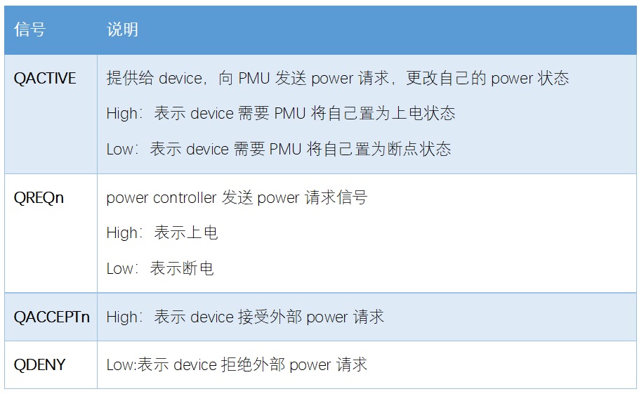
为支持dynamic retention模式,A15, A17采用了Q-channel这样一个比较简单灵活的接口,与STANDBYWFI这样的信号通信相比,Q-channel允许控制器可以根据设备的工作状态或系统状态,发出低功耗请求;设备可以根据自己的工作状态,从而决定是否接受请求。Q-channel接口提供了控制器和设备的握手机制。
Q-channel比较简单。对于时钟控制来说,只有打开和关闭两种状态就可以了。对于电源控制来说,只有ON和OFF两种状态。
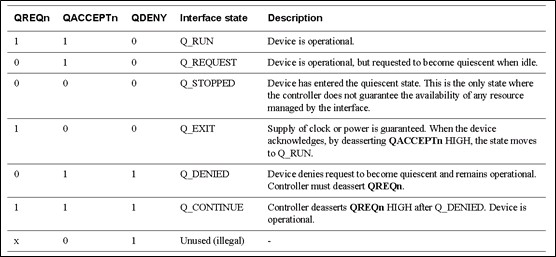
Q-Channelinterface定义了几种握手状态:
Q_RUN: device处于上电状态。
Q_REQUEST: device处于上电状态,但是在idle状态时,可以接收power request,进入断电状态。
Q_STOPPED: device进入了断电状态。
Q_EXIT: 等待被提供时钟或者power的状态。当device得到外部提供的时钟或者power时,将QACCEPTn拉高,进入Q_RUN状态。
Q_DENIED: device拒绝外部power的请求,不进入断电状态,而保持上电状态。
Q_CONTINUE: PMU在Q_DENIED状态后,将QREQn拉高后的状态。
A15, A17提供了单个CPU核和L2 cluster级用于retention握手的Q-channel接口。以单个核retention为例:
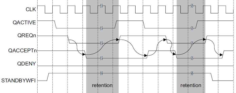
当A15核进入WFI低功耗状态,其时钟停止时,QACTIVE被拉低,用于指示此核可以进入retention模式。外部power controller可以拉低QREQn请求将核置为retention,A15通过将QACCEPTn拉低接受retention请求。当QREQn和QACCEPTn都为低时,A15处于静默(quiescent)状态,只要QREQn保持在低状态,A15的时钟保持停止。外部power controller可以安全低将电压降低到retention级别。
如果当QREQn为低时,单个核不能安全地进入静默状态,它可以将QDENY拉高。这样power controller就不能降低此核的电压。
在A7+A1x big.LITTLE系统设计中,因为有更复杂的电源管理模式的组合和模式,为了灵活的系统设计,一般power controller系统会基于MCU(如Cortex-M0, Cortex-M3的子系统)设置,这样可以通过MCU软件firmware来灵活处理电源管理请求。这个MCU一般设置为always on的电源域。
A53+A57/A7x 系统
A53+A57/A72/A73的电源管理硬件机制和A7+A17比较类似,基本上也是通过STANDBYWFI, STANDBYWFIL2, ACINACTM (ACE接口,如果是配置为CHI接口时,信号为SINACT),Q-channel(用于retention)等这些信号与power controller通讯。
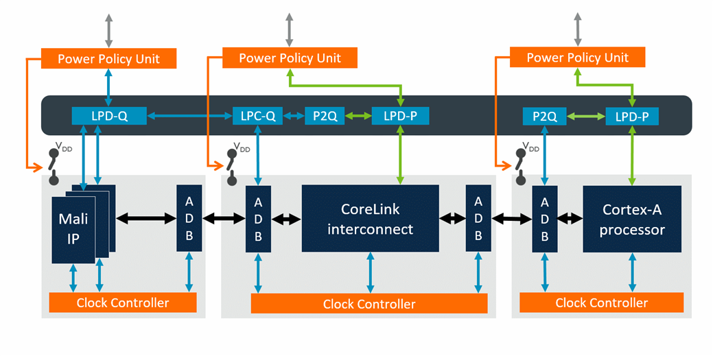
一个变化是,arm开始推出power policy unit(PPU)这样的标准电源管理组件。
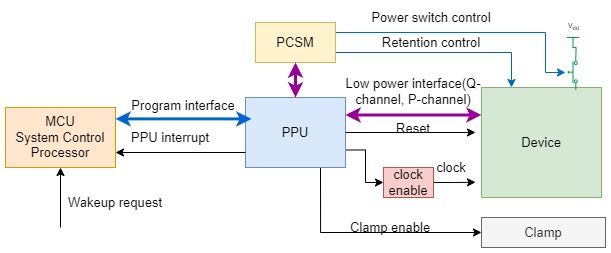
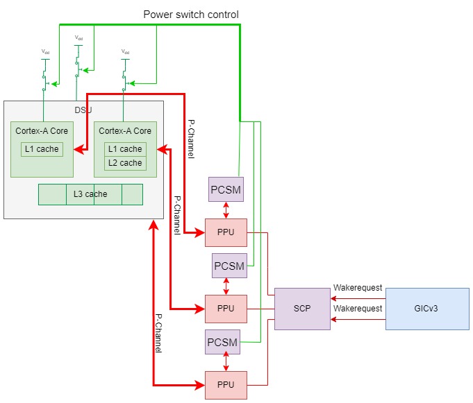
PPU提供一个配置接口给SCP,用于功耗策略控制和配置。其次,PPU与设备之间的控制接口,包括低功耗接口(low power interface,简称LPI),若干组Q-channel和一组P-channel,还有时钟/复位控制。最后,还有一个与功耗状态机之间的P-channel接口。
PPU刚开始是在arm自己的开发平台Juno(A53+A57和A53+A72)上设置使用的,后来arm以此为基础推出了PPU规范。
PPU的接口:
1.系统控制器(System Control Processor, SCP)的配置通路,可以访问PPU寄存器接口,一般是APB
2.PPU可以发送中断,处理完一次电源管理事件后了可以通过中断通知SCP
3. PPU与被管理的设备间需要一个通信接口,就是LPI(Low Power Interface, Q-channel或者 P-channel),取决于需要实现的具体功能是什么。
4. PPU还会提供时钟控制,复位和Clamp控制(如果需要实现电源关断)给被管理的设备.
- PCSM(Power Control State Machine)的接口,PPU通过P-channel来告诉PCSM当前的状态,PCSM根据PPU的状态决定何时控制电源关断,retention控制
A53+A57/A72/A73系统上,CPU还基本还是使用STANDBYWFI, STANDBYWFIL2, ACINACTM这些信号,因此需要在SoC集成时将这些信号转接到PPU或SCP上。后面的DynamIQ处理器就不再使用这些信号,而直接利用P-Channel和Q-channel.
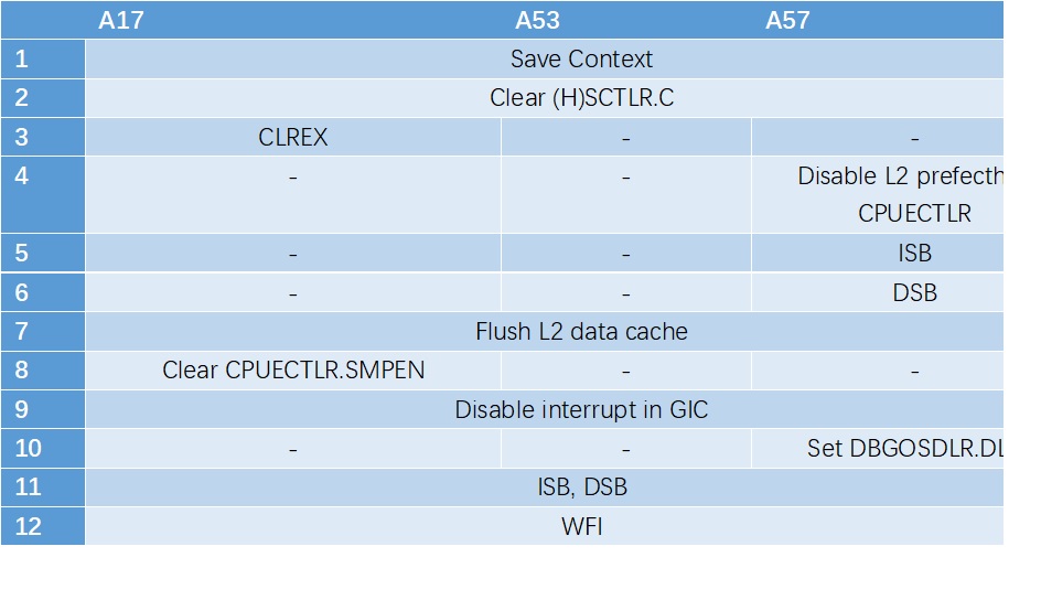
在power down流程上,虽然A7, A15, A17, A53, A57, A72大致相同,但是有一些和微构架相关的配置有所不同,从而导致不同CPU core的power down流程不能复用。以下表格总结来自各CPU的使用手册。
DynamIQ系统
第二代big.LITTLE系统DynamIQ的电源管理接口标准化为Q-Channel和P-Channel. DynamIQ处理器将L3 cahce包含在DSU cluster中,而L3 cache可以被硬件划为多个区,可以单独关掉部分和全部的L3 cache,比如1/4, 1/2 L3 cache. 这带来更加复杂的电源模式。
Q-channel过于简单了。对于时钟控制来说,只有打开和关闭两种状态就可以了。但是对于电源控制来说,只有ON和OFF两种状态,对于某些复杂的power控制场景来说就不够用了。要对DSU L3实现全上电,半上电,1/4上电等操作。这时,Q-channel就不够用了,arm定义了P-channel来解决这个问题。
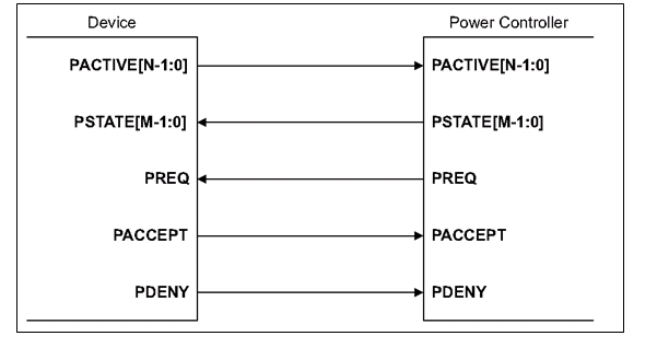
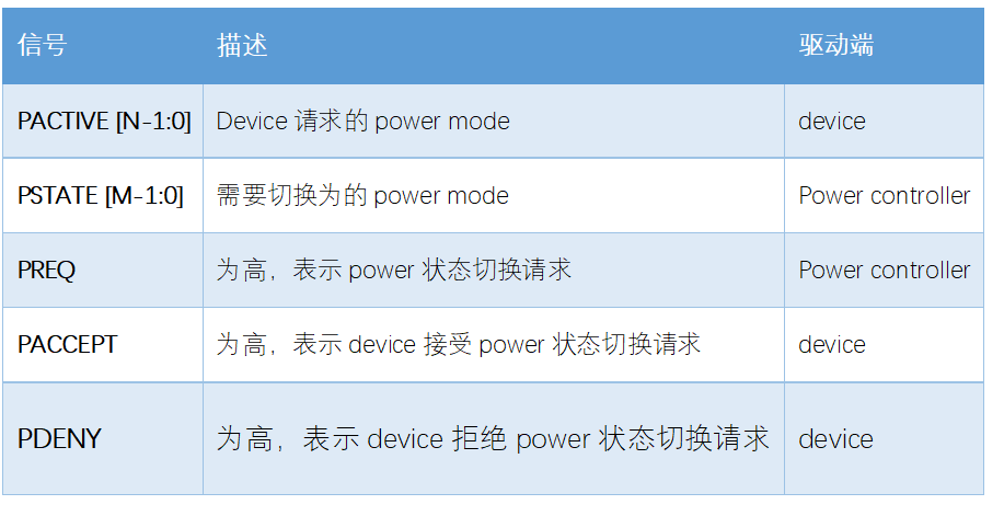
相比Q-channel,P-channel把PACTIVE信号加宽了,不再是一根信号,设备可以传递更多的工作状态给控制器;控制器会额外多发出一组PSTATE信号,描述切换power状态的请求。
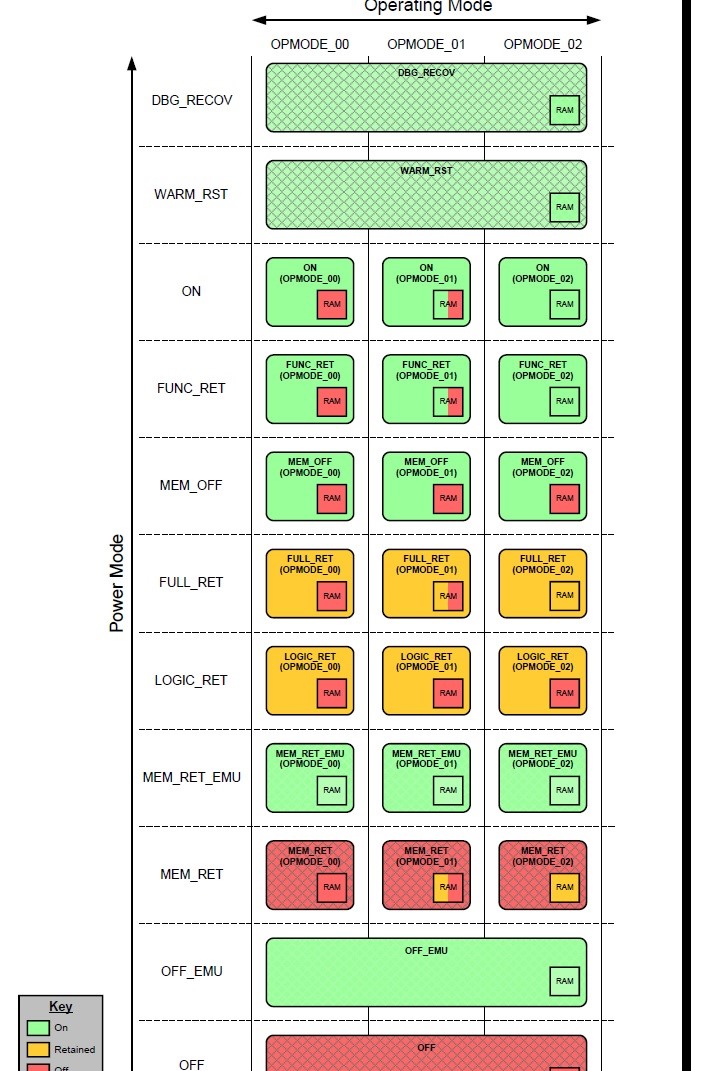
PPU定义了两个模式:电源模式(power mode)和操作模式(operating mode)。电源模式是一个电源域里logic和RAM电源状态的正常组合,以及相关的时钟、复位和隔离控制。而操作模式代表电源模式的配置。例如,在电源模式是ON的时候,Full L3 cache ON, 1/2 L3 cache ON, 1/4 L3 cache ON是电源模式ON的三种操作模式。
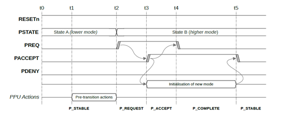
P_Channel接口如下
PACCEPT和PDENY在握手中,只能有一个为高。PACCEPT表示接受请求,PDENY表示拒绝请求.
DynamIQ处理器系统中,每个CPU core都有对应的P-channel, DSU cluster层面还有一个P-channel。DynamIQ CPU core在PACTIVE信号上提供当前要求power mode, power controller可以通过PREQ和PSTATE表示决定和要求的改变。CPU硬件然后进行这个电源模式的必要操作,例如停掉时钟,涮cache,退出一致性维护等。
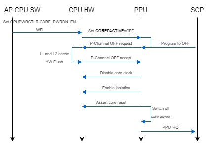
以一个CPU核的power down为例:
1. 运行在这个核上的软件保护寄存器上下文之后,设置CPUPWRCTLR 寄存器的CORE_PWRDN_EN bit, 然后执行WFI指令。这会导致CPU的COREPACTIVE输出表示可以进入到OFF电源模式
2. PPU通过P-Channel请求OFF
3. CPU hardware进行自动硬件L1数据cache和L2 cache的flush操作
4. 这个CPU硬件将自己退出cluster一致性维护
5. CPU核通过assert COREACCEPT表示接受OFF模式
6. PPU停止CPU核的clock,使能钳位/隔离逻辑,assert CPU核reset信号
7. PPU控制PCSM切断CPU核的电源
8. 如果需要的话,PPU可以发送一个中断给SCP,通知SCP电源模式转换完成
DynamIQ系统硬件设计还让电源管理软件流程更加简单,标准化,不需要像之前A1x, A5x, A7x CPU power down流程需要做一些微构架相关的操作。
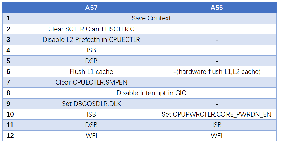
下面以A57和A55为例,看一下它们power down 流程的区别。
由上面对比可知,DynamIQ的CPU比之前的CPU流程更加简单,因为很多原来流程需要做的事情都被硬件自动完成,不需要软件参与。
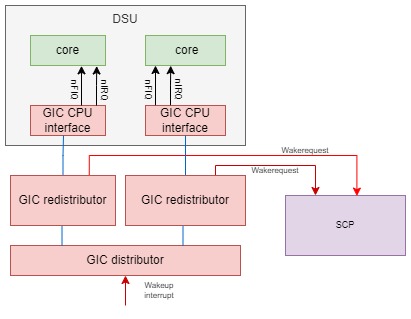
DynamIQ系统普遍使用GICv3中断控制器。GICv3中断控制器相对之前GICv2,设置了专门的wakeup request接口(GICv2利用nIRQOUT, nFIQOUT作为wakeup输入),同时GICv3也有了专门的寄存器GICR_WAKER给软件来设置某个GIC CPU interface对应的CPU核的power on/power down状态。在CPU核power down/power up的软件流程中,需要设置GICR_WAKER寄存器来将GIC CPU interface和Redistibutor的连接断开。当CPU核在power down状态,且GICR_WAKER做了相应的设置时,发送给这个CPU核的wakeup interrupt,不再发送给GIC CPU interface,而是由GIC Redistributor通过wakerequest信号发送给SCP,从而让SCP给这个CPU核上电。
Arm设计了PCK-600 IP,让客户可以更简单地获取和利用PPU集成到系统中。
Armv9 DynamIQ系统
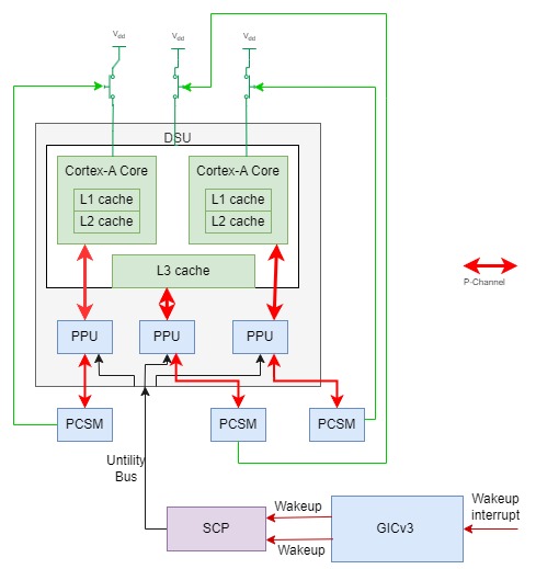
Armv9 DynamIQ系统在之前DynamIQ的基础上更近一步,直接将每个核一个的PPU和DSU cluster级的PPU集成到了DSU cluster里面,从而不需要SoC设计者去集成PPU。在DSU cluster总线接口上提供了新的Utility Bus让SCP可以通过它访问PPU的寄存器。
总结
Arm的电源管理硬件设计是
1、 每种CPU有自己独特设计,通过各种信号线与power controller交互的方式进化为采用标准的P-Channel,Q-Channel的交互方式
2、 由每个SoC特有的电源控制logic到采用标准PPU组件的方式
3、 由简单单核电源控制到多核,到big.LITTLE, DynamIQ的复杂电源控制过程
4、 通过硬件来简化软件电源管理的流程的过程

