WS2812 LED
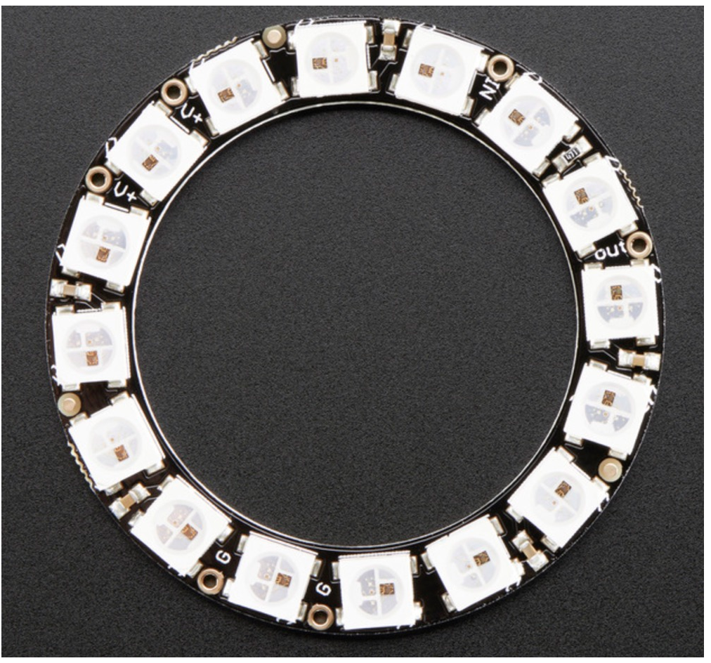
WS2812 LED是一种全彩的LED,我们平时看到的很多彩灯以及点阵就是这样的,因此第一个实践案例用来做这个真的不错。
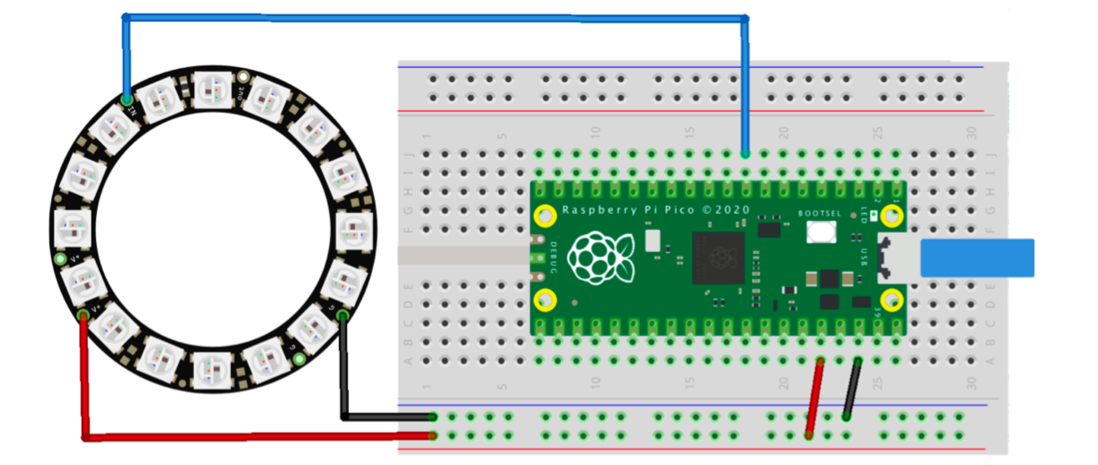
电气接线图:
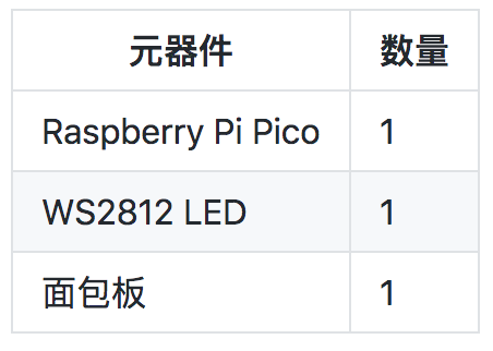
材料清单:
demo程序:
import array, time
from machine import Pin
import rp2

# Configure the number of WS2812 LEDs.
NUM_LEDS = 16
PIN_NUM = 6
brightness = 0.2

@rp2.asm_pio(sideset_init=rp2.PIO.OUT_LOW, out_shiftdir=rp2.PIO.SHIFT_LEFT, autopull=True, pull_thresh=24)
def ws2812():
    T1 = 2
    T2 = 5
    T3 = 3
    wrap_target()
    label("bitloop")
    out(x, 1)               .side(0)    [T3 - 1]
    jmp(not_x, "do_zero")   .side(1)    [T1 - 1]
    jmp("bitloop")          .side(1)    [T2 - 1]
    label("do_zero")
    nop()                   .side(0)    [T2 - 1]
    wrap()


# Create the StateMachine with the ws2812 program, outputting on pin
sm = rp2.StateMachine(0, ws2812, freq=8_000_000, sideset_base=Pin(PIN_NUM))

# Start the StateMachine, it will wait for data on its FIFO.
sm.active(1)

# Display a pattern on the LEDs via an array of LED RGB values.
ar = array.array("I", [0 for _ in range(NUM_LEDS)])

##########################################################################
def pixels_show():
    dimmer_ar = array.array("I", [0 for _ in range(NUM_LEDS)])
    for i,c in enumerate(ar):
        r = int(((c >> 8) & 0xFF) * brightness)
        g = int(((c >> 16) & 0xFF) * brightness)
        b = int((c & 0xFF) * brightness)
        dimmer_ar[i] = (g<<16) + (r<<8) + b
    sm.put(dimmer_ar, 8)
    time.sleep_ms(10)

def pixels_set(i, color):
    ar[i] = (color[1]<<16) + (color[0]<<8) + color[2]

def pixels_fill(color):
    for i in range(len(ar)):
        pixels_set(i, color)

def color_chase(color, wait):
    for i in range(NUM_LEDS):
        pixels_set(i, color)
        time.sleep(wait)
        pixels_show()
    time.sleep(0.2)

def wheel(pos):
    # Input a value 0 to 255 to get a color value.
    # The colours are a transition r - g - b - back to r.
    if pos < 0 or pos > 255:
        return (0, 0, 0)
    if pos < 85:
        return (255 - pos * 3, pos * 3, 0)
    if pos < 170:
        pos -= 85
        return (0, 255 - pos * 3, pos * 3)
    pos -= 170
    return (pos * 3, 0, 255 - pos * 3)


def rainbow_cycle(wait):
    for j in range(255):
        for i in range(NUM_LEDS):
            rc_index = (i * 256 // NUM_LEDS) + j
            pixels_set(i, wheel(rc_index & 255))
        pixels_show()
        time.sleep(wait)

BLACK = (0, 0, 0)
RED = (255, 0, 0)
YELLOW = (255, 150, 0)
GREEN = (0, 255, 0)
CYAN = (0, 255, 255)
BLUE = (0, 0, 255)
PURPLE = (180, 0, 255)
WHITE = (255, 255, 255)
COLORS = (BLACK, RED, YELLOW, GREEN, CYAN, BLUE, PURPLE, WHITE)

print("fills")
for color in COLORS:
    pixels_fill(color)
    pixels_show()
    time.sleep(0.2)

print("chases")
for color in COLORS:
    color_chase(color, 0.01)

print("rainbow")
rainbow_cycle(0)
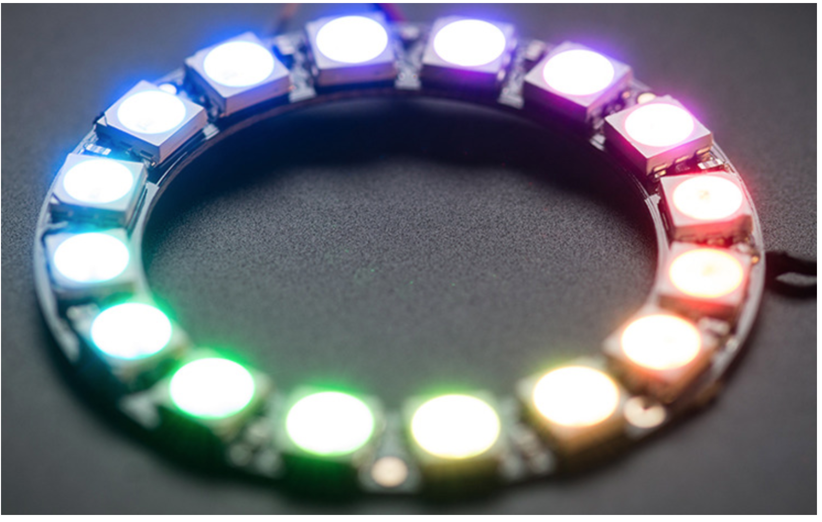
效果:
DHT系列的温湿度传感器
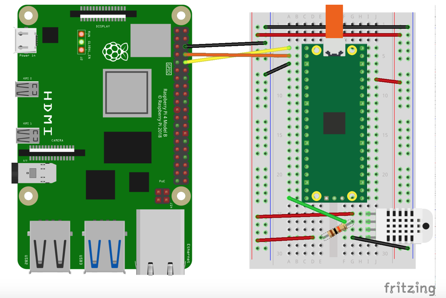
DHT11、DHT21系列的传感器小伙伴们一定很熟悉,单片机一接,写个小的APP,可以做个小型的室内温湿度监测系统。
材料清单:
电气接线图:
Demo:
#include <stdio.h>
#include <math.h>
#include "pico/stdlib.h"
#include "hardware/gpio.h"

const uint LED_PIN = PICO_DEFAULT_LED_PIN;
const uint DHT_PIN = 15;
const uint MAX_TIMINGS = 85;

typedef struct {
    float humidity;
    float temp_celsius;
} dht_reading;

void read_from_dht(dht_reading *result);

int main() {
    stdio_init_all();
    gpio_init(LED_PIN);
    gpio_init(DHT_PIN);
    gpio_set_dir(LED_PIN, GPIO_OUT);
    while (1) {
        dht_reading reading;
        read_from_dht(&reading);
        float fahrenheit = (reading.temp_celsius * 9 / 5) + 32;
        printf("Humidity = %.1f%%, Temperature = %.1fC (%.1fF)\n",
               reading.humidity, reading.temp_celsius, fahrenheit);

        sleep_ms(2000);
    }
}

void read_from_dht(dht_reading *result) {
    int data[5] = {0, 0, 0, 0, 0};
    uint last = 1;
    uint j = 0;

    gpio_set_dir(DHT_PIN, GPIO_OUT);
    gpio_put(DHT_PIN, 0);
    sleep_ms(20);
    gpio_set_dir(DHT_PIN, GPIO_IN);

    gpio_put(LED_PIN, 1);
    for (uint i = 0; i < MAX_TIMINGS; i++) {
        uint count = 0;
        while (gpio_get(DHT_PIN) == last) {
            count++;
            sleep_us(1);
            if (count == 255) break;
        }
        last = gpio_get(DHT_PIN);
        if (count == 255) break;

        if ((i >= 4) && (i % 2 == 0)) {
            data[j / 8] <<= 1;
            if (count > 16) data[j / 8] |= 1;
            j++;
        }
    }
    gpio_put(LED_PIN, 0);

    if ((j >= 40) && (data[4] == ((data[0] + data[1] + data[2] + data[3]) & 0xFF))) {
        result->humidity = (float) ((data[0] << 8) + data[1]) / 10;
        if (result->humidity > 100) {
            result->humidity = data[0];
        }
        result->temp_celsius = (float) (((data[2] & 0x7F) << 8) + data[3]) / 10;
        if (result->temp_celsius > 125) {
            result->temp_celsius = data[2];
        }
        if (data[2] & 0x80) {
            result->temp_celsius = -result->temp_celsius;
        }
    } else {
        printf("Bad data\n");
    }
}
CMakelist.txt:
add_executable(dht
        dht.c
        )

target_link_libraries(dht pico_stdlib)

pico_add_extra_outputs(dht)

# add url via pico_set_program_url
example_auto_set_url(dht)
终端的输出如下:
MPU9250
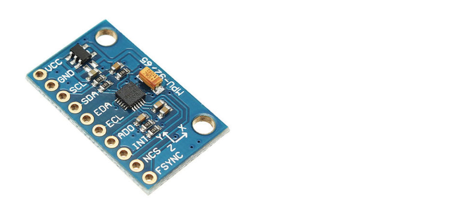
平衡车、手机体感、旋翼无人机的平衡主要靠陀螺模组,MPU9250是一款常用的9轴姿态测量单元。MPU9250有两个内部时钟源,以及一个PLL。
时钟的选择需要综合平衡 时钟精度和功耗两个因素,所以从MPU9250的性能参数可以看到,一旦Gyro开启,功耗都是在mA级别,而加速度计和磁力计都是在uA级别的功耗。
电气元件:
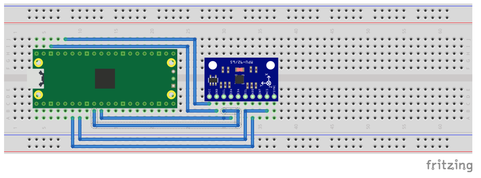
电气接线图:
demo:
#include <stdio.h>
#include <string.h>
#include "pico/stdlib.h"
#include "hardware/spi.h"
#define PIN_MISO 4
#define PIN_CS 5
#define PIN_SCK 6
#define PIN_MOSI 7
#define SPI_PORT spi0
#define READ_BIT 0x80
static inline void cs_select() {
asm volatile("nop \n nop \n nop");
gpio_put(PIN_CS, 0); // Active low
asm volatile("nop \n nop \n nop");
}
static inline void cs_deselect() {
asm volatile("nop \n nop \n nop");
gpio_put(PIN_CS, 1);
asm volatile("nop \n nop \n nop");
}
static void mpu9250_reset() {
// Two byte reset. First byte register, second byte data
// There are a load more options to set up the device in different ways that could be added here
uint8_t buf[] = {0x6B, 0x00};
cs_select();
spi_write_blocking(SPI_PORT, buf, 2);
cs_deselect();
}
static void read_registers(uint8_t reg, uint8_t *buf, uint16_t len) {
reg |= READ_BIT;
cs_select();
spi_write_blocking(SPI_PORT, ®, 1);
sleep_ms(10);
spi_read_blocking(SPI_PORT, 0, buf, len);
cs_deselect();
sleep_ms(10);
}
static void mpu9250_read_raw(int16_t accel[3], int16_t gyro[3], int16_t *temp) {
uint8_t buffer[6];
// Start reading acceleration registers from register 0x3B for 6 bytes
read_registers(0x3B, buffer, 6);
for (int i = 0; i < 3; i++) {
accel[i] = (buffer[i * 2] << 8 | buffer[(i * 2) + 1]);
}
// Now gyro data from reg 0x43 for 6 bytes
read_registers(0x43, buffer, 6);
for (int i = 0; i < 3; i++) {
gyro[i] = (buffer[i * 2] << 8 | buffer[(i * 2) + 1]);;
}
// Now temperature from reg 0x41 for 2 bytes
read_registers(0x41, buffer, 2);
*temp = buffer[0] << 8 | buffer[1];
}
int main() {
stdio_init_all();
printf("Hello, MPU9250! Reading raw data from registers via SPI...\n");
// This example will use SPI0 at 0.5MHz.
spi_init(SPI_PORT, 500 * 1000);
gpio_set_function(PIN_MISO, GPIO_FUNC_SPI);
gpio_set_function(PIN_SCK, GPIO_FUNC_SPI);
gpio_set_function(PIN_MOSI, GPIO_FUNC_SPI);
// Chip select is active-low, so we'll initialise it to a driven-high state
gpio_init(PIN_CS);
gpio_set_dir(PIN_CS, GPIO_OUT);
gpio_put(PIN_CS, 1);
mpu9250_reset();
// See if SPI is working - interrograte the device for its I2C ID number, should be 0x71
uint8_t id;
read_registers(0x75, &id, 1);
printf("I2C address is 0x%x\n", id);
int16_t acceleration[3], gyro[3], temp;
while (1) {
mpu9250_read_raw(acceleration, gyro, &temp);
// These are the raw numbers from the chip, so will need tweaking to be really useful.
// See the datasheet for more information
printf("Acc. X = %d, Y = %d, Z = %d\n", acceleration[0], acceleration[1], acceleration[2]);
printf("Gyro. X = %d, Y = %d, Z = %d\n", gyro[0], gyro[1], gyro[2]);
// Temperature is simple so use the datasheet calculation to get deg C.
// Note this is chip temperature.
printf("Temp. = %f\n", (temp / 340.0) + 36.53);
sleep_ms(100);
}
return 0;
}CMakeLists.txt:
add_executable(mpu9250_spi
        mpu9250_spi.c
        )

# Pull in our (to be renamed) simple get you started dependencies
target_link_libraries(mpu9250_spi pico_stdlib hardware_spi)

# create map/bin/hex file etc.
pico_add_extra_outputs(mpu9250_spi)

# add url via pico_set_program_url
example_auto_set_url(mpu9250_spi)本文转自:Github
作者:zihan987
推荐阅读
- Raspberry Pi Pico教程高级篇:ADC&PWM
- Raspberry Pi Pico教程进阶篇:I2C&SPI
- 阿chai带你学Raspberry Pi Pico基础篇:IO口的使用/UART通信/中断/定时器
更多嵌入式AI技术相关内容请关注嵌入式AI专栏。

