原文地址:https://vlsitutorials.com/example-showing-jtag-operation/, 后附英文原文。
通过此前一系列文章熟悉 JTAG 架构后,让我们用一个完整的示例来了解用于 Debug 访问的 TAP 是如何工作的。
假设这么一个调试场景,我们出于调试需求,需要 JTAG 能够访问并修改设计中一个 3 比特位宽的控制信号。在正常的 functional 模式中,该控制信号数值为 3'b111;但出于一些调试目的,我们想要把它改成 3'b100。以下是通过 TAP 实现这一点的过程。
假设设计中的 JTAG 指令寄存器(IR)位宽为 4 比特。首先我们需要在 JTAG 设计中增加一个 3 比特位宽的用户数据寄存器(User DR),并将其输出连接到我们想要修改的控制信号上。接下来,我们为该 User DR 指定一个 opcode,比如 4'b1010(因为 IR 为 4 比特,因此 opcode 同样为 4 比特)。在设计中添加该 User DR 时,需要将其复位值设定为 3'b111(为什么?复位值对应于该控制信号在 functional 模式中需要的数值,即 3'b111)。这样一来,User DR 在任何 JTAG Update 事件更改数值前,将驱动该信号为 3'b111。一般来说,在芯片上电过程中,JTAG 会比其他逻辑更早退出复位状态,因此,该控制信号能赶在被其驱动的逻辑退出复位之前,确保其数值为所需的 3'b111。
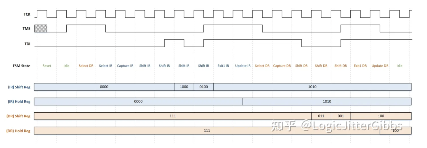
图 1- 示例的时序图
图 1 中的时序图展示了如何将 User DR 的数值更新为 3‘b100 的过程。该时序图来自 JTAG 工业标准,其中的 TMS 和 TDI 以及 IR/DR Hold Register 在时钟下降沿更新数值,而 FSM 状态以及 IR/DR Hold Register 则在时钟上升沿跳变数值。
图 1 中的 16-状态 FSM 从 Test-Logic Reset 状态开始工作,通过设置 TMS 的时序使状态机进入 Shift IR 状态。接下来通过 TDI 端口数据寄存器对应的 opcode(4’b1010)移入指令寄存器。shift 和 hold 寄存器的初始值均为复位值 0,4'b1010 由从 LSB 到 MSB 的顺序串行地移入指令寄存器中。通过设置 TMS 的时序使状态机进入 Update IR 状态。在 Update IR 状态中,IR 的 hold 寄存器更新为 Shift 寄存器中的值,指令译码器解码该指令的数值,建立起一条 TDI 和用户数据寄存器之间的通路。接下来,FSM 退出 Update IR 状态,转移至 Shift DR 状态,此时串行地向 DR shift 寄存器中移入所需的数值 3'b100,由从 LSB 到 MSB 的顺序。 在数据 3'b100 完全加载到 Shift 寄存器中后,FSM 跳转到 Update DR 状态。在该状态中,DR hold 寄存器更新为 3'b100,就在此时,需要修改的控制信号数值也从复位值 3’b111 改变为 3'b100。
原文
Now that we are familiar with the JTAG architecture, let us take an example to understand how TAP can be used for some debug access. Suppose there is a 3-bit control signal in a design that we want to have the access to modify for some debug purpose. Assume that during normal functional operation the control signal should be 3’b111; but for some debug purpose we want to change it to, say 3’b100. Let’s see how we can do that using Test Access Ports.
Assume we have a 4-bit Instruction Register (IR) in our JTAG. First we have to create a 3-bit User Data Register (User DR) in our JTAG and connect it to the control signal that we want to modify. Then we have to assign an opcode to the User DR, say 1010 (4-bit opcode as we have a 4-bit IR). While creating the User DR, we have to ensure that the reset value of the register is 3’b111 (Why? Because as mentioned above during normal functional operation the control signal should be 3’b111). The User DR drives 3’b111 to the control signal until we update the DR with another value; typically in a chip power on process the JTAG comes out of reset first before any other logic, so the control signal inside our logic will get its required value of 3’b111 before the functional logic comes out of reset.
Figure 1: Timing diagram for the given example
The timing diagram in Figure 1 shows how to update the User Data Register with value 3’b100. This timing diagram is from an industry standard JTAG where the TMS, TDI and Hold Register of DR and IR changes value at the nededge of the clock, whereas the FSM and Shift Register of DR and IR works at the posedge of the clock.
We started from the Test-Logic Reset state of the 16 state FSM discussed here and reached the Shift IR state by setting the TMS to the required value. Then through the TDI, we shifted-in the opcode (4’b1010) of the User Data Register into the Instruction Register. Initially the shift register and hold register of the IR was zero, which is its reset value; 4’b1010 was shifted in serially from LSB to MSB. Once the required opcode was loaded into the shift register of IR, we moved to the Update IR state by changing the TMS value. In the Update IR state the hold register of IR was updated with the value present in its shift register. Then the Instruction Decoder decoded this value and established a path between TDI and the User Data Register. Then we exited the Update IR state and moved to the Shift DR state, where we serially loaded our required value of 3’b100 into the shift register of User DR from LSB to MSB. Once 3’b100 was loaded into the shift register, we moved to the Update DR state. In Update DR state the hold register of DR is updated with 3’b100 and at this point only the control signal value changed from 3’b111 to 3’b100.
原文:知乎
作者:LogicJitterGibbs
相关文章推荐
- JTAG Architecture //JTAG 架构
- FPGA单独下载<固化文件>的解决方案
- Xilinx DDS Compiler IP 使用教程
- 还在为没有项目做发愁?这几个神级开源网站,都是FPGA/IC项目
- Vitis AI-FPGA实时智能零售系统
更多FPGA干货请关注FPGA的逻辑技术专栏。欢迎添加极术小姐姐微信(id:aijishu20)加入技术交流群,请备注研究方向。


