原文地址:https://vlsitutorials.com/constraining-logically-exclusive-clocks-in-synthesis/
后附英文原文
本文是 how to define Synthesis timing constraint 系列文章的第五篇。
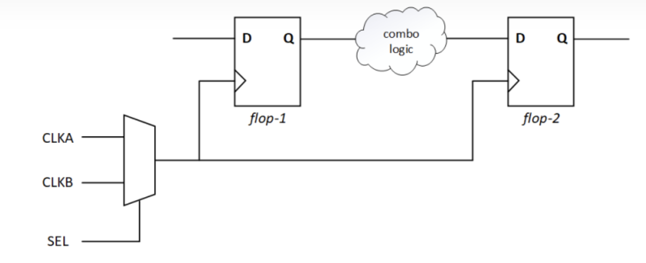
逻辑无关的时钟(Logically exclusive clocks)是指在设计中同时工作,但是之间没有交互路径的时钟们。在存在逻辑无关的时钟的设计中,常见到时钟接到多路选择器 (MUX)的输入端,通过 MUX 的 SEL 端来决定所使用的时钟。需要注意的一项重要准则是,逻辑无关的时钟不应该在 MUX 以外的地方有交互的时序路径。
图1
在图 1 所示的电路中,有两个时钟 CLKA 和 CLKB,通过 MUX 选择输出时钟,也就是说设计中可能使用 CLKA,也可能使用 CLKB。用户可以通过 set_case_analysis 约束 MUX 的 SEL 端为 0 或者 1,来选择约束使用 CLKA 或者 CLKB。在约束了 SEL 端的值后,综合工具只会对所使用的时钟进行时序分析。然而,如果没有 SEL 端的约束值,那么两个时钟都被允许在时序分析中到达所有 FF 的时钟端,两者都可以是时序路径中的发送或者采样时钟。所以,时序分析工具在做最差路径分析时,会考虑所有可能的发送和采样时钟的排列组合。换句话说,通过 MUX 相连的时钟不会被综合工具自动推断为逻辑无关时钟,因此综合工具会考虑以下四种发送和采样时钟情况:
当然,中间两种排列组合其实不用出现。所以,综合工具只需考虑 CLKA->CLKA 和 CLKB->CLKB 两种时钟排列组合,只优化这两种时钟组合的最差情况,我们通过以下约束使综合工具实现这一点:
set_clock_groups -logically_exclusive -group CLKA -group CLKB通过以上约束,两种触发器之间延迟仅会为 CLKA->CLKA 和 CLKB->CLKB 两种时钟排列组合进行优化。
注意:对于上一个例子,可选地,我们也可以通过以下两条约束来实现上面一条约束语句的功能:
set_false_path -from [get_clocks CLKA] -to [get_clocks CLKB] set_false_path -from [get_clocks CLKB] -to [get_clocks CLKA]
图 2
图 2 中是另一种情况的例子,两个时钟在 MUX 之外也有交互路径,如果我们还是使用之前的约束 ”set_clock_groups -logically_exclusive -group CLKA -group CLKB“,那么综合工具只会考虑 CLKA->CLKA 和 CLKB->CLKB 两种情况下的组合逻辑优化。但在上图的例子中,CLKA 从 flop-3 处发送的数据,其到 flop-2 处被 CLKB 采样的路径,CLKA -> CLKB 也可能是最差的时序情况,因此需要被综合器进行优化。
因此,我们需要在 MUX 处定义一个新的创建时钟:
create_generated_clock -name -CLKA_GEN -source CLKA [get_pins clk_mux/out] create_generated_clock -name -CLKB_GEN -source CLKB [get_pins clk_mux/out]我们只需要将经过 MUX 之后的 CLKA,CLKB 之间设置成逻辑无关时钟。
set_clock_groups -logically_exclusive -group CLKA_GEN -group CLKB_GEN
图 3
在图 3 的示例中,有两对独立 2 选 1 的时钟,由 SEL1 控制的 CLKA 和 CLKB,以及 SEL2 控制的 CLKC 和 CLKD。注意,在上图的设计中,CLKA 或者 CLKB 驱动的触发器和 CLKC 或者 CLKD 驱动的触发器之间有时序路径,反之亦然。
对于上述设计,我们创建两组独立的逻辑无关时钟组
set_clock_groups -logically_exclusive -group CLKA -group CLKB set_clock_groups -logically_exclusive -group CLKC -group CLKD在每组时钟之间,综合工具会对可能的最差时序路径进行优化。
注意:对于上一个例子,我们也可以通过以下四条 false path 约束来实现上面一条约束语句的功能:
set_false_path -from [get_clocks CLKA] -to [get_clocks CLKB] set_false_path -from [get_clocks CLKB] -to [get_clocks CLKA] set_false_path -from [get_clocks CLKC] -to [get_clocks CLKD] set_false_path -from [get_clocks CLKD] -to [get_clocks CLKC]
图 4 中的设计相比图 3 做了一点微小的改动,注意两个 MUX 的 SEL 端是连在一起,而不是独立的。
此时设计中可能共存的时钟组合是 CLKA & CLKC,以及 CLKB & CLKD。
这里,我们根据两组时钟组合,约束了两组组时序无关的时钟组
set_clock_groups -logically_exclusive -group “CLKA CLKC” -group “CLKB CLKD”时钟组之间时钟可能存在交互路径,但是时钟组之间的时钟不会有交互。此处,CLKA 和 CLKC 之间会有交互路径,但是 CLKA 或者 CLKC 不能和 CLKB 或者 CLKD 交互,反之亦然。
注意:对于上一个例子,我们也可以通过四个时钟之间八条 false path 约束来实现上面一条约束语句的功能,这里不再一一罗列。
原文
This is article-5 of how to define Synthesis timing constraint
Logically exclusive clocks are active in the design but cannot interact with each other. When dealing with logically exclusive clock, one often sees a mux with the select line determining which clock is active. An important guideline to remember while dealing with logically exclusive clocks is that logically exclusive clocks shouldn’t interact outside the mux.
Figure 1
Consider the example shown in Figure 1, we have two clocks – CLKA and CLKB that are muxed, such that the design either operates either at CLKA or at CLKB. The user has the option to use a set_case_analysis constraint and apply a value of 0 or 1 to choose either between CLKA or CLKB; if this is done, then for timing analysis only the selected clock will be used by the synthesis tool. However if the select port is unconstrained, then both clocks are allowed to reach both the flip-flop’s clock pin, and either of the two clocks can be independently used as launch or capture clock edges, so the timing analysis will consider all the possible combination for worst case timing; in other words, muxed clocks are not inferred as exclusive clocks automatically for timing analysis. As a result, the synthesis optimization will consider all the following four cases –
Of course, the two middle cases can never happen. So, to direct the synthesis tool to consider only CLKA → CLKA and CLKB → CLKB and to optimize the worst of those two cases only, we need to use –
set_clock_groups -logically_exclusive -group CLKA -group CLKBBy doing this the delay between the two registers will be optimized for the worst of CLKA → CLKA or CLKB → CLKB
Note: Alternatively, we can also apply two false paths for this case –
set_false_path -from [get_clocks CLKA] -to [get_clocks CLKB] set_false_path -from [get_clocks CLKB] -to [get_clocks CLKA]
Figure 2
Consider the example shown in Figure 2, where the clocks interact outside the mux. If we use the constraint “set_clock_groups -logically_exclusive -group CLKA -group CLKB”, then the synthesis tool will consider only CLKA → CLKA and CLKB → CLKB will optimize the combination logic for the worst of those two cases only. But there is possibility that the data being launched in flop-3 at CLKA and being captured at flop-2 at CLKB is the worst-case scenario and therefore the combinational logic should be optimized accordingly.
Therefore, we need to create generated clocks for CLKA and CLKB, at the output of the mux –
create_generated_clock -name -CLKA_GEN -source CLKA [get_pins clk_mux/out] create_generated_clock -name -CLKB_GEN -source CLKB [get_pins clk_mux/out]
Then only we need set the two generated clocks as logically exclusive –
set_clock_groups -logically_exclusive -group CLKA_GEN -group CLKB_GEN
Figure 3
Consider the example shown in Figure 3, there are two pairs of clocks that are being independently muxed. CLKA and CLKB is controlled by SEL1 and CLKC and CLKD is controlled by SEL2. Notice that inside our design, the flops that are driven by CLKA or CLKB that communicate with flops being captured by CLKC or CLKD and vice-versa.
To constrain this design, we create two separate logically exclusive clock groups –
set_clock_groups -logically_exclusive -group CLKA -group CLKB set_clock_groups -logically_exclusive -group CLKC -group CLKDAnd the delay of each path will be optimized for the worst of the logically possible timing conditions.
Note: Alternatively, we can also apply four false paths for this case –
set_false_path -from [get_clocks CLKA] -to [get_clocks CLKB] set_false_path -from [get_clocks CLKB] -to [get_clocks CLKA] set_false_path -from [get_clocks CLKC] -to [get_clocks CLKD] set_false_path -from [get_clocks CLKD] -to [get_clocks CLKC]
Figure 4
Consider the example shown in Figure 4, we have made one small change compared to the example shown in Figure 3; notice that the select line of the muxes, instead of being independent are now connected to each other.
Here we need to create a logically exclusive group between groups containing CLKA & CLKC and another containing CLKB & CLKD –
set_clock_groups -logically_exclusive -group “CLKA CLKC” -group “CLKB CLKD”Clocks within the group can communicate with each other but clocks across groups cannot. So here CLKA and CLKC can talk to each other but neither CLKA nor CLKC can communicate to CLKB or CLKD (or vice versa).
Note: It will take eight different set_false_path commands to accomplish the same thing that we can do using one set_clock_groups command
原文:知乎
作者:LogicJitterGibbs
相关文章推荐
- 【译文】如何定义综合时序约束·目录
- [译文】DRAM Circuit Design: A Tutorial 前言与目录
- [译文】在综合中约束多路同步时钟时序路径
- [译文】在综合中约束时序路径 1
- 从招股书了解龙迅半导体(三):市场、供应链与客户
更多FPGA干货请关注FPGA的逻辑技术专栏。欢迎添加极术小姐姐微信(id:aijishu20)加入技术交流群,请备注研究方向。


