原文地址:https://vlsitutorials.com/constraining-multi-cycle-path-in-synthesis/
后附英文原文
本文是 how to define Synthesis timing constraint 系列文章的第六篇。
多周期路径(MCP,Multi-Cycle Path)指的是触发器之间的组合逻辑延迟允许超过一个时钟周期的Flip2Flip 路径。一般情况下,对于一些延迟很大的组合逻辑路径,从数据源端到终点,可以允许它们的传播时延达到多个周期的时间。与 false path 不同,多周期路径是有效的路径,并且一定会被综合工具检查,只是检查不是只在一个时钟周期内进行。
图 1:原始电路
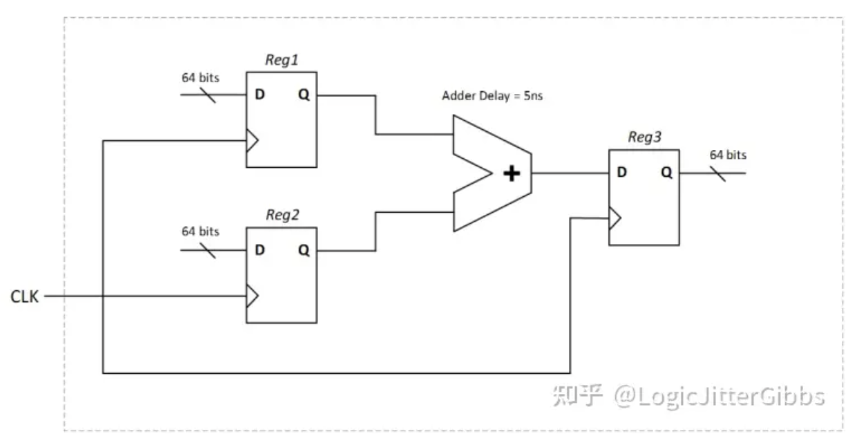
图 1 是一个两组 64 位总线之间的加法电路,其中只有一个周期为 2ns 的时钟。输入加法器的加数在进入加法器之前有一级锁存触发器,同时加法器的输出也是经过锁存的。加法器的最大延迟大约是 5ns,因为时钟周期只有 2ns,所以在一个周期内不可能实现时序的收敛。
图 2:经过改进的,采用多周期设计的电路
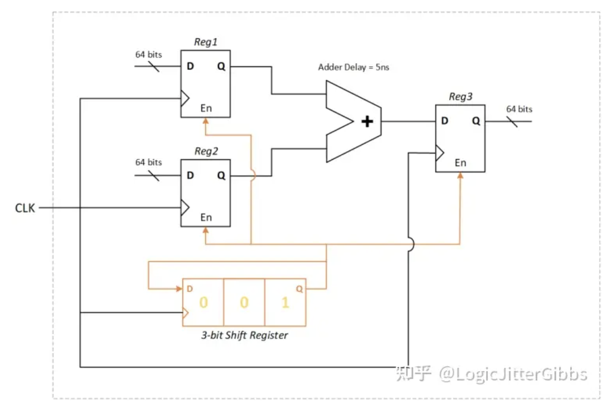
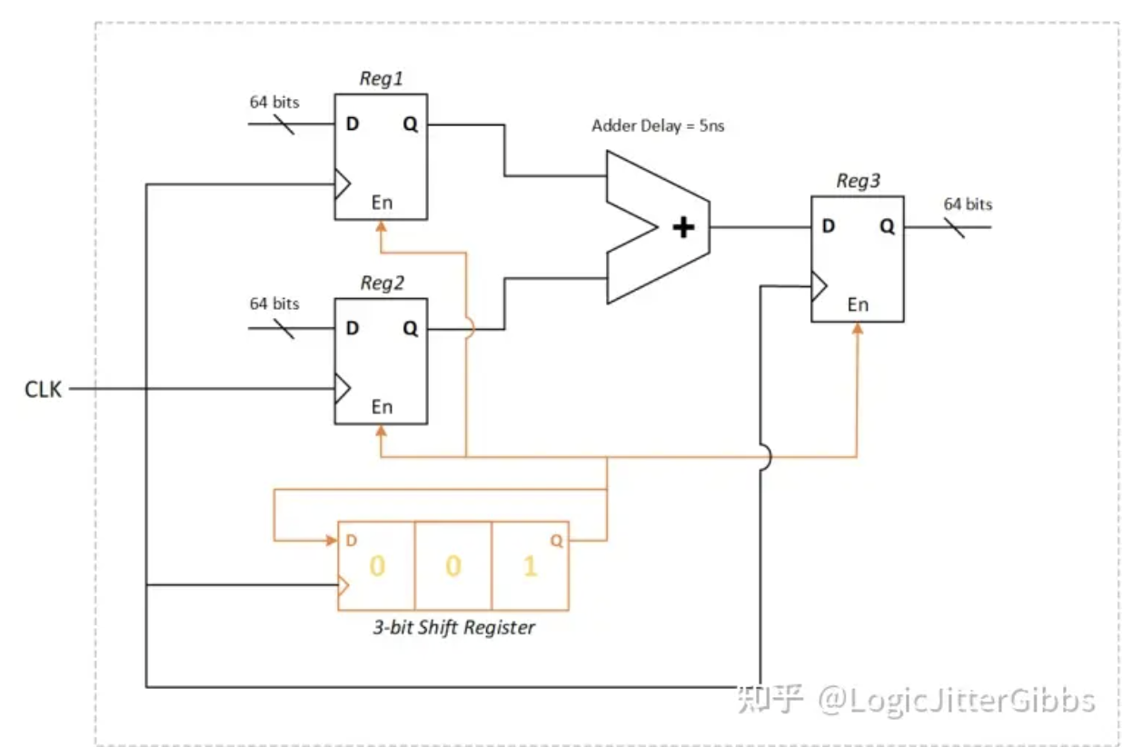
为了使加法器的输出时钟正确,我们需要将其修改,采用多周期运算的方式。所有的触发器增加了一个共同的使能比特,使能比特由一个三比特的移位寄存器控制,其初始装填数值为 001,并且有一个从输出端到输入端的反馈环路,此例中,enable 比特每三个周期置起一次。
如果我们只是简单地采用 create_clock -period 2 [get_ports CLK] 约束,综合工具没有办法分析出设计中的使能逻辑,从而理解加法器的建立时序在三个周期内完成收敛就可以满足设计(这是因为综合工具并不会进行动态的逻辑仿真)。因此,综合工具会尽力尝试去优化加法器逻辑,希望能够在默认的单周期建立时间内收敛时序,但这是不可能,也没有必要的。
因此,我们需要在输入寄存器和输出寄存器之间添加多周期路径,这可以通过 set_multicycle_path 约束实现,指定建立数值为 3(对应 3 个时钟周期),作用于这条起于 Reg1 和 Reg2,终于 Reg3 的路径约束为
set_multicycle_path -setup 3 -from {Reg1[*] Reg2[*]} -to Reg3[*]注意:其中,[] 中的 是通配符,表示该约束作用于该寄存器的所有 64 比特。
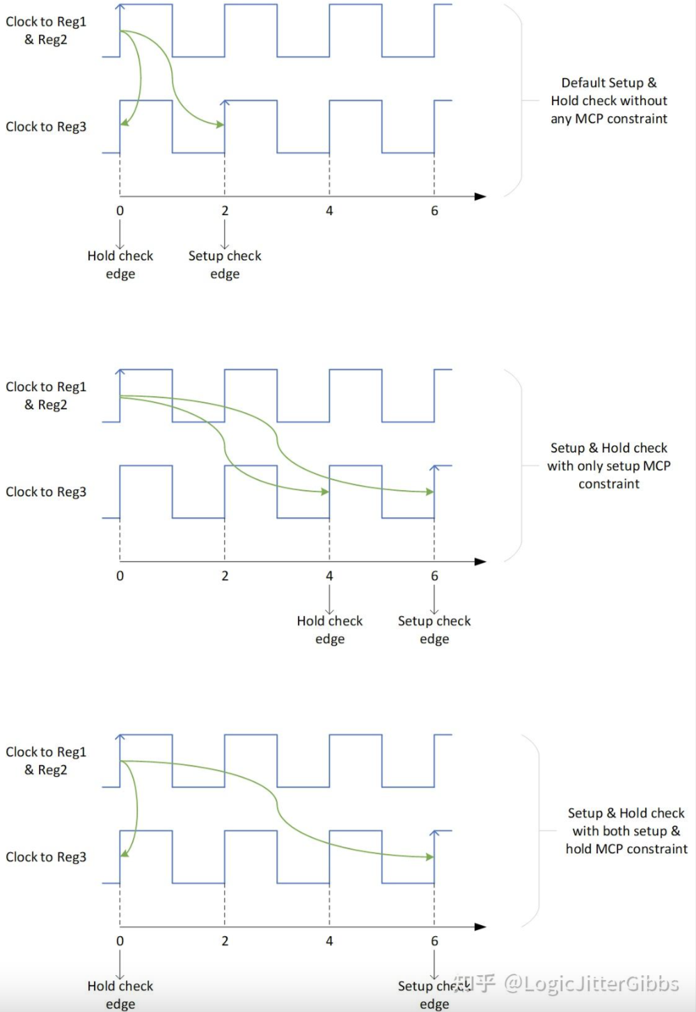
默认情况下,在没有 MCP 约束时,综合工具在源时钟的发送时钟边沿,和采样时钟的下一个时钟边沿之间进行 Setup 时序检查。Hold 时序检查则在源时钟的发送时钟边沿,和采样时钟的相同时钟边沿之间进行。换句话说,我们可以认为 Hold 时序分析和 Setup 时序分析在同一个时钟周期内进行。(译注:译者认为这里指的是 hold 的检查时钟沿和 Setup 检查时钟沿间隔一个周期,并且 hold 的检查时钟沿会随 setup 检查时钟边沿后移而后移)
接下来详细分析一下 MCP 的 Hold 检查时钟边沿,假设我们设置了一个建立周期数值为 N 的多周期约束,那么默认的 Hold 检查边沿会随之移动到采样时钟的第 N-1 个周期。此时 Hold 检查的要求变得更严格,要求路径上的延迟更大,所以我们需要综合工具在路径上插入更多 Buffer,这就会导致没有必要的面积以及功耗的增加。一般来说,我们只需要把建立时间检查移动到第 N 个采样时钟边沿,而保持时间检查仍然只需要在第 0 个采样时钟边沿进行。所以,我们需要分别设置多周期约束的保持和建立数值。
回到上述的示例中,我们已经把建立时间检查边沿移到了第三个时钟周期(在 6ns),因此 Hold 检查时钟边沿被综合工具自动移到了 4ns 处,和建立时间检查边沿差一个时钟周期。这意味着 64 比特的加法器的最快路径在最快条件下,需要慢于 4ns 加上 Reg1/Reg2 的保持时间。实际上这是没有必要的,因为采样寄存器有 enable 逻辑来控制下一次的采样时间,因此即使下一个数据提前到 0ns 和 6ns 之间到来,触发器也不会采样,所以我们并不担心保持时序违例带来的潜在亚稳态问题。基于上述原因,我们只需要保持时间检查在发送时钟的同一个时钟边沿进行,也就是把保持检查时钟边沿前移两个时钟周期,我们通过下述约束实现
set_multicycle_path -hold 2 -from {Reg1[*] Reg2[*]} -to Reg3[*]此处我们将 Hold 检查数值设置为 2,意味着 Hold 检查时钟边沿相比默认 Hold 检查时钟边沿前移两个周期。而默认的时钟边沿(当 Hold 数值为 0 时,或者没有对 Hold 时钟沿进行专门约束时)在建立时钟检查边沿的前一个周期。所以在很多情况下,我们需要各自对多周期建立和保持检查边沿进行约束,从而调整 Hold 检查边沿。
图 3: 不同情况下建立检查和保持检查时钟边沿示意图
原文
This is article-6 of how to define Synthesis timing constraint
A Multi-Cycle Path (MCP) is a flop-to-flop path, where the combinational logic delay in between the flops is permissible to take more than one clock cycle. Sometimes timing paths with large delays are designed such that they are permitted multiple cycles to propagate from source to destination. Unlike false paths, multicycle paths are valid and must be analyzed, but against more than one clock period.
Figure 1: The original circuit
Consider an example as shown in Figure 1, where we have only one clock (of 2ns period) in our design and we are performing a 64-bit addition of two buses. The input buses to the adder, as well as the output bus from the adder are registered. The maximum delay of the adder is estimated to be around 5ns, and the period of the register clock is 2ns. Since the adder delay in more than time period of the clock, it is not possible to close the timing within one clock cycle.
Figure 2: The modified circuit with multi-cycle design approach
For the circuit to operate correctly, a multi-cycle design approach was implemented. All the registers have a commonly connected enable bit, which is being controlled by a 3-bit shift register, which is preloaded with 001 and has a feedback loop from output to the input; this causes the enable signal to go high every 3 cycles.
If we simply apply a “create_clock -period 2 [get_ports CLK]” constraint, the synthesis tool will not analyze the enable control logic to understand that the adder has 3 cycles for setup check timing closure (as the tool doesn’t perform dynamic logic simulation). Therefore, it will try to optimize the adder logic to close setup time within 1 clock cycle, which is not possible (and unnecessary).
Therefore, we need to add multi cycle paths between the input registers and the output register. This is done by the set_multicycle_path command and by specifying a setup value of 3 (corresponding to 3 cycles), which is then applied on the paths which start at Reg1 & Reg2 and end at Reg3, as shown below –
set_multicycle_path -setup 3 -from {Reg1[*] Reg2[*]} -to Reg3[*]Note: The [*] is added to consider all the bits (64 bits) of the registers.
By default (without any MCP constraint), setup checks are measured from the source clock edge to the destination’s next clock edge and hold checks are measured from the source clock edge to the destination’s same clock edge. In other words, we can also say hold timing analysis is performed in the same clock period where setup timing is performed.
Let’s say that a multi cycle path setup of N was applied, if no explicit hold multi cycle path is set, the default hold check will be performed at (N-1)th edge of destination clock. In order to meet this hold requirement, additional buffers will be added by the synthesis tool, which un-necessarily increases area, power etc. Typically, we only want to move the setup to the Nth edge of the destination clock and the hold check needs to be at the 0th edge of destination clock. In order to do this, we need to specify both the setup and hold multi cycle path constraint.
In the example we discussed, we have moved the setup capturing clock edge to the 3rd cycle (at 6ns), therefore the hold timing analysis is done by the synthesis tool at 4ns, which is within the same cycle as setup capturing edge. But this would mean the fastest path through this 64 bits adder under the fastest operating condition has to be slower than (4ns + hold time of Reg1 or Reg2), which is not necessary, as the registers are enabled registers, therefore we are not concerned about the possibility of metastability due to hold violation if the data happens to arrive right at one of the earlier clock edges between 0ns and 6ns. So, we want the hold check to be performed at the same edge as the launching edge; to move the hold check back by 2 clock cycles, we need to use –
set_multicycle_path -hold 2 -from {Reg1[*] Reg2[*]} -to Reg3[*]The default value of this hold option is 0, which means that the hold check is to be performed within the same cycle as the setup check, or in other words one clock cycle before the setup capturing clock edge happens. Therefore, the guideline here is to specify both the setup and hold multi cycle path constraints, if we want the correct analysis by the timing engine tool.
Figure 3: Timing diagram illustrating the setup check and hold check edge under different conditions
原文:知乎
作者:LogicJitterGibbs
相关文章推荐
- 【译文】 在综合中约束逻辑无关时钟
- 【译文】如何定义综合时序约束·目录
- [译文】DRAM Circuit Design: A Tutorial 前言与目录
- [译文】在综合中约束多路同步时钟时序路径
- [译文】在综合中约束时序路径 1
更多FPGA干货请关注FPGA的逻辑技术专栏。欢迎添加极术小姐姐微信(id:aijishu20)加入技术交流群,请备注研究方向。


