原文地址:https://vlsitutorials.com/scan-on-chip-clock-controller/, 后附英文原文。
OCC,On-chip Clock Controllers,片上时钟控制器,也被称为 SCC,Scan Clock Controllers。OCC 是插入到 SoC 中的时钟控制逻辑,用于硅片在 ATE (Automatic test Equipment)机台上进行测试时,控制测试使用的时钟。因为在 at-speed 测试时,在 capture 阶段需要用到两个和功能(functional)时钟频率相同的两个脉冲,如果没有 OCC,那么我们只能通过芯片的 I/O 引脚(PAD)灌入这两个 at-speed 脉冲。但是通过 PAD 灌入的脉冲,在时钟频率上会受到限制。而在有 OCC 的情况下,我们可以通过 OCC 控制内部 PLL,来产生测试用的时钟脉冲。在 stuck-at 测试期间,OCC 会保证在 Capture 阶段只产生一个脉冲,同样地, 在 at-speed 测试期间,OCC 保证只在 capture 阶段产生两个脉冲,其频率等于功能时钟的频率。
因此,在具有可测试性的设计中,所有的测试时钟都要通过 OCC ,并在 sacn 模式(包括 stuck-at 测试和 at-speed 测试)中受其控制,而在功能模式中则旁路输出功能时钟。关于如何修改设计的时钟结构,添加 OCC,使其更具有可测试性,可以通过这篇文章了解。
在本文中,我们会讨论一个非常基础的 OCC 结构设计,只能为了展示其基本的工作原理。事实上,工业界实际使用的标准 OCC 比本文讨论的基础结构更复杂先进,对于时钟毛刺有更好的鲁棒性。

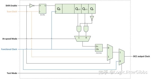
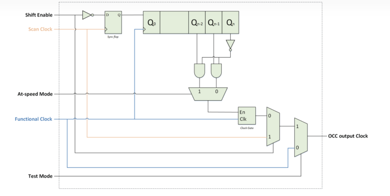
图 1:具有 n-bit 移位寄存器的基础 OCC 结构示意图
当电路出于功能模式时(Test Mode = 0),OCC 旁路功能时钟直接输出(如图 1 所示)。而在 shift 阶段时(Shift Enable = 1),OCC 选择 Scan 时钟输出。当电路处于 capture 阶段时(Shift Enable = 0),移位寄存器开始向后不断移入 1,在满足条件后打开时钟门控,输出一个或者两个时钟脉冲。具体是一个还是两个,则取决于当前测试的类型,stuck-at 测试 (At-speed Mode = 0) 时为 1 个脉冲,而 at-speed 测试 (At-speed Mode = 1) 时则为 2 个脉冲。
图 2 展示了 OCC 在 at-speed 测试时的行为,该 OCC 的移位寄存器宽度为 5 比特。在 5 个功能时钟的上升沿后,产生两个 capture 脉冲(因为使用的移位寄存器宽度为 5 比特,所以是 5 个功能时钟周期后产生)。
注意:在 shift Enable 信号置低后(此时 Test Mode 信号时钟始终保持 1),移位寄存器的宽度将决定在功能时钟从 OCC 输出后,延迟多少个周期输出 capture 脉冲。

图 2: 图 1 的 OCC 结构(5-bit 移位寄存器)的仿真波形
OCC 的 Systemverilog 代码:
module occ
#(
   parameter SHIFT_REG_BITS = 5
 )
 (
   input logic test_mode,
   input logic atspeed_mode,
   input logic shift_en,
   input logic scan_clk,
   input logic func_clk,
   output logic occ_out_clk
 )
   logic cg_en;
   logic cg_out_clk;
   logic sync_flop;
   logic [SHIFT_REG_BITS-1:0]shift_reg;

   always @(func_clk or cg_en) begin
     if (cg_en == 1)
       cg_out_clk = func_clk;
     else
       cg_out_clk = 0;
   end

   always_ff @(posedge scan_clk) begin
     sync_flop <= ~shift_en;
   end

   always_ff @(posedge func_clk) begin
     shift_reg <= shift_reg << 1;
     shift_reg[0] <= sync_flop;
   end

   assign occ_out_clk = test_mode ? (shift_en ? scan_clk : cg_out_clk) : func_clk;

   assign cg_en = atspeed_mode ? (~shift_reg[SHIFT_REG_BITS-1] &  shift_reg[SHIFT_REG_BITS-3]) : (~shift_reg[SHIFT_REG_BITS-1] &  shift_reg[SHIFT_REG_BITS-2]);

 endmodule
原文
On-chip Clock Controllers (OCC) are also known as Scan Clock Controllers (SCC). OCC is the logic inserted on the SOC for controlling clocks during silicon testing on ATE (Automatic test Equipment). Since at-speed testing requires two clock pulses in capture mode with a frequency equal to the functional clock frequency, without OCC we need to provide these at-speed pulses through I/O pads. But these pads has limitation in terms of maximum frequency they can support; OCC on other hand uses internal PLL clock for generating clock pulses for test. During stuck-at testing, the OCC ensures only one clock pulse is generated in the capture phase. Similarly, during at-speed testing, the OCC ensures two clock pulses are generated in the capture phase, having a frequency equal to frequency of the functional clock.
Therefore all the test clocks in a scan friendly design is routed through an OCC, which controls the clock operation in scan mode (both in stuck-at and at-speed testing) and bypasses the functional clock in functional mode. You can check here, how the clocking architecture is modified with OCCs to support scan.
In this article we will be discussing about a very basic OCC design with the sole purpose of demonstrating how it work. However industry standard OCCs are much more advanced and robust to clock glitches than the OCC discussed here.

Figure 1: Schematic of a basic On-chip Clock Controller structure (having a n-bit shift register)
When the circuit is in functional mode (Test Mode = 0), the OCC bypasses the functional clock (Refer Figure 1). But during the shift phase (Shift Enable = 1), the Scan Clock is propagated at the output of OCC. In capture phase (Shift Enable = 0), the shift register starts shifting ‘1’ and enables the Clock Gate, to allow single pulse or double pulse, depending on the type of testing. The OCC generates one clock pulse in stuck-at testing (At-speed Mode = 0) and two clock pulses in at-speed testing (At-speed Mode = 1).
The behavior of this OCC (having a 5-bit shift register) in at-speed testing is shown in Figure 2. The two capture pulses came after 5 positive edges of the functional clock (as we are using a 5-bit shift register).
NOTE: Once the Shift Enable is asserted Low, the n-bit shift register decides the delay in terms of the number of positive edges of the functional clock, after which the functional clock is propagated at the output of the OCC.

Figure 2: Simulation waveform of the OCC structure shown in Figure 1 (having a 5-bit shift register)
Systemverilog code of the OCC:
module occ
#(
   parameter SHIFT_REG_BITS = 5
 )
 (
   input logic test_mode,
   input logic atspeed_mode,
   input logic shift_en,
   input logic scan_clk,
   input logic func_clk,
   output logic occ_out_clk
 )
   logic cg_en;
   logic cg_out_clk;
   logic sync_flop;
   logic [SHIFT_REG_BITS-1:0]shift_reg;

   always @(func_clk or cg_en) begin
     if (cg_en == 1)
       cg_out_clk = func_clk;
     else
       cg_out_clk = 0;
   end

   always_ff @(posedge scan_clk) begin
     sync_flop <= ~shift_en;
   end

   always_ff @(posedge func_clk) begin
     shift_reg <= shift_reg << 1;
     shift_reg[0] <= sync_flop;
   end

   assign occ_out_clk = test_mode ? (shift_en ? scan_clk : cg_out_clk) : func_clk;

   assign cg_en = atspeed_mode ? (~shift_reg[SHIFT_REG_BITS-1] &  shift_reg[SHIFT_REG_BITS-3]) : (~shift_reg[SHIFT_REG_BITS-1] &  shift_reg[SHIFT_REG_BITS-2]);

 endmodule
原文:知乎
作者:LogicJitterGibbs
相关文章推荐
- 【译文】PCI Express Technology 3.0 Chapter 8 事务排序
- 【译文】 DFT, Scan and ATPG
- 【译文】 Example showing JTAG Operation // JTAG 运行示例
- JTAG Architecture //JTAG 架构
- 【译文】 Scan Clocking Architecture // Scan 时钟架构案
更多FPGA干货请关注FPGA的逻辑技术专栏。欢迎添加极术小姐姐微信(id:aijishu20)加入技术交流群,请备注研究方向。


